Reference | INSPECTION USING OSCILLOSCOPE
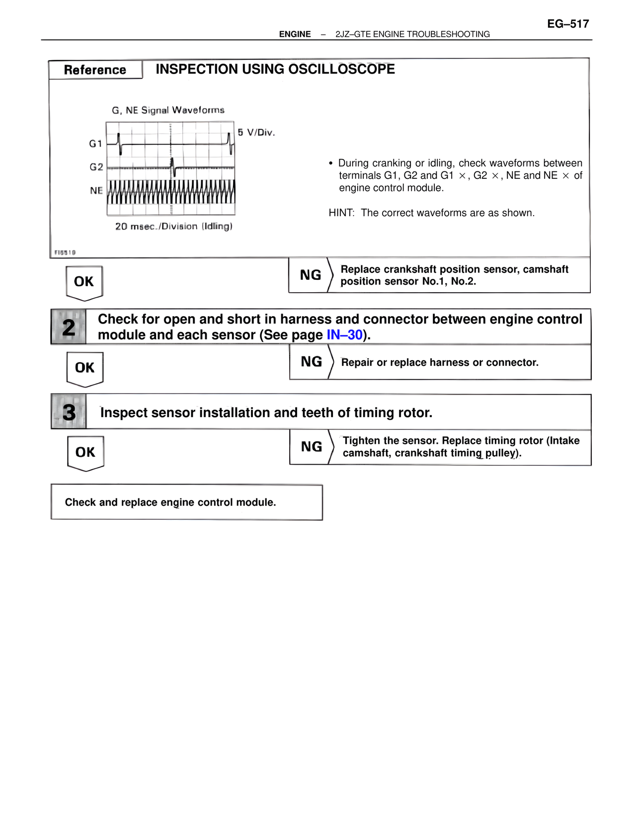
G, NE Signal Waveforms
5 V/Div.
G1
G2
NE
20 msec./Division (Idling)
FI6519
• During cranking or idling, check waveforms between terminals G1, G2 and G1 ×, G2 ×, NE and NE × of engine control module.
HINT: The correct waveforms are as shown.
OK
NG Replace crankshaft position sensor, camshaft position sensor No.1, No.2.
2 Check for open and short in harness and connector between engine control module and each sensor (See page IN–30).
OK
NG Repair or replace harness or connector.
3 Inspect sensor installation and teeth of timing rotor.
OK
NG Tighten the sensor. Replace timing rotor (Intake camshaft, crankshaft timing pulley).
Check and replace engine control module.