EG–525
ENGINE – 2JZ–GTE ENGINE TROUBLESHOOTING
DTC 21 Main Heated Oxygen Sensor Circuit
CIRCUIT DESCRIPTION
To obtain a high purification rate for the CO, HC and NOx components of the exhaust gas, a three–way catalytic converter is used, but for most efficient use of the three–way catalytic converter, the air–fuel ratio must be precisely controlled so that it is always close to the stoichiometric air–fuel ratio.
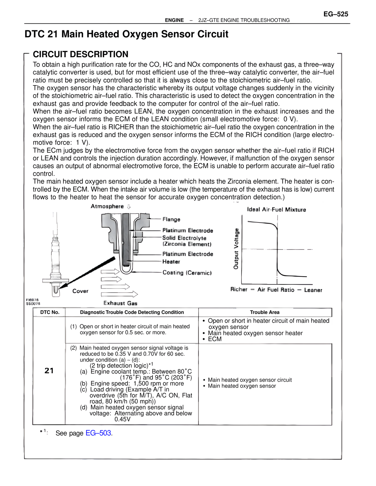
The oxygen sensor has the characteristic whereby its output voltage changes suddenly in the vicinity of the stoichiometric air–fuel ratio. This characteristic is used to detect the oxygen concentration in the exhaust gas and provide feedback to the computer for control of the air–fuel ratio.
When the air–fuel ratio becomes LEAN, the oxygen concentration in the exhaust increases and the oxygen sensor informs the ECM of the LEAN condition (small electromotive force: 0 V).
When the air–fuel ratio is RICHER than the stoichiometric air–fuel ratio the oxygen concentration in the exhaust gas is reduced and the oxygen sensor informs the ECM of the RICH condition (large electromotive force: 1 V).
The ECm judges by the electromotive force from the oxygen sensor whether the air–fuel ratio if RICH or LEAN and controls the injection duration accordingly. However, if malfunction of the oxygen sensor causes an output of abnormal electromotive force, the ECM is unable to perform accurate air–fuel ratio control.
The main heated oxygen sensor include a heater which heats the Zirconia element. The heater is controlled by the ECM. When the intake air volume is low (the temperature of the exhaust has is low) current flows to the heater to heat the sensor for accurate oxygen concentration detection.)
Atmosphere
Flange
Platinum Electrode
Solid Electrolyte
(Zirconia Element)
Platinum Electrode
Heater
Coating (Ceramic)
Cover
Exhaust Gas
Ideal Air-Fuel Mixture
Output Voltage
Richer — Air Fuel Ratio — Leaner
F86978
SS0076
DTC No. | Diagnostic Trouble Code Detecting Condition | Trouble Area
(1) Open or short in heater circuit of main heated oxygen sensor for 0.5 sec. or more.
• Open or short in heater circuit of main heated oxygen sensor
• Main heated oxygen sensor heater
• ECM
21
(2) Main heated oxygen sensor signal voltage is reduced to be 0.35 V and 0.70V for 60 sec. under condition (a) ~ (d):
(2 trip detection logic)*1
(a) Engine coolant temp.: Between 80°C (176°F) and 95°C (203°F)
(b) Engine speed: 1,500 rpm or more
(c) Load driving (Example A/T in overdrive (5th for M/T), A/C ON, Flat road, 80 km/h (50 mph))
(d) Main heated oxygen sensor signal voltage: Alternating above and below 0.45V
• Main heated oxygen sensor circuit
• Main heated oxygen sensor
*1: See page EG–503.