INSPECTION PROCEDURE
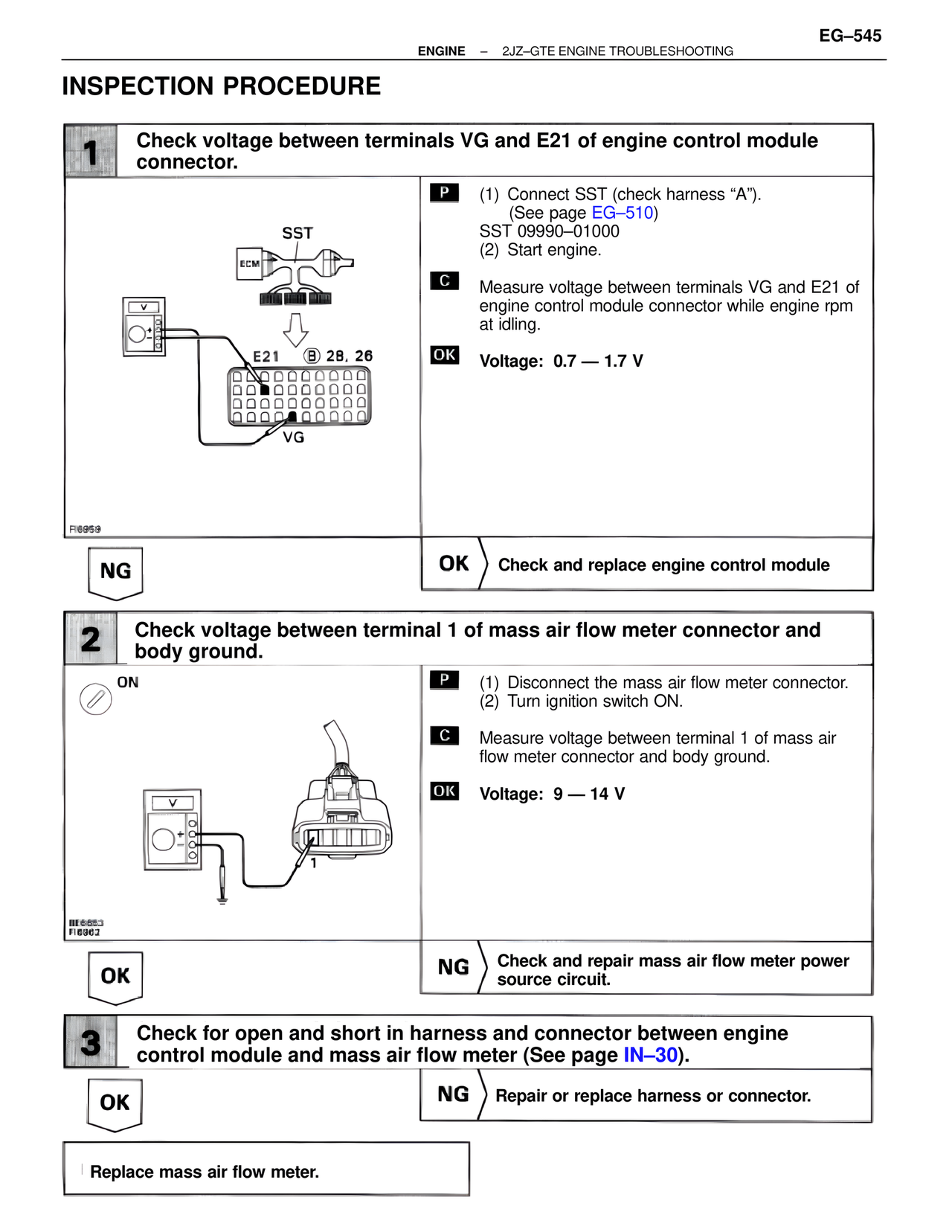
1 Check voltage between terminals VG and E21 of engine control module connector.
SST
ECM
E21 B 28, 26
VG
FI6959
P (1) Connect SST (check harness "A").
(See page EG–510)
SST 09990–01000
(2) Start engine.
C Measure voltage between terminals VG and E21 of engine control module connector while engine rpm at idling.
OK Voltage: 0.7 — 1.7 V
NG OK Check and replace engine control module
2 Check voltage between terminal 1 of mass air flow meter connector and body ground.
ON
BE6653
FI6962
P (1) Disconnect the mass air flow meter connector.
(2) Turn ignition switch ON.
C Measure voltage between terminal 1 of mass air flow meter connector and body ground.
OK Voltage: 9 — 14 V
OK NG Check and repair mass air flow meter power source circuit.
3 Check for open and short in harness and connector between engine control module and mass air flow meter (See page IN–30).
OK NG Repair or replace harness or connector.
Replace mass air flow meter.