DTC 51 Switch Condition Signal Circuit
CIRCUIT DESCRIPTION
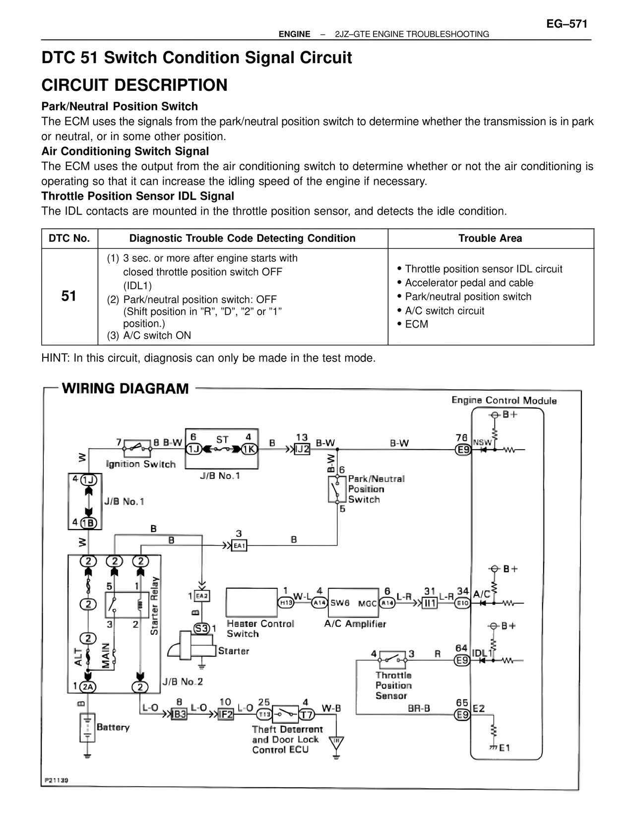
Park/Neutral Position Switch
The ECM uses the signals from the park/neutral position switch to determine whether the transmission is in park or neutral, or in some other position.
Air Conditioning Switch Signal
The ECM uses the output from the air conditioning switch to determine whether or not the air conditioning is operating so that it can increase the idling speed of the engine if necessary.
Throttle Position Sensor IDL Signal
The IDL contacts are mounted in the throttle position sensor, and detects the idle condition.
DTC No. | Diagnostic Trouble Code Detecting Condition | Trouble Area
51 | (1) 3 sec. or more after engine starts with closed throttle position switch OFF (IDL1)
(2) Park/neutral position switch: OFF (Shift position in "R", "D", "2" or "1" position.)
(3) A/C switch ON | • Throttle position sensor IDL circuit
• Accelerator pedal and cable
• Park/neutral position switch
• A/C switch circuit
• ECM
HINT: In this circuit, diagnosis can only be made in the test mode.
WIRING DIAGRAM
Engine Control Module
B+
76 NSW
E9
7 B B-W 6 ST 4 B 13 B-W B-W
1J 1K J2
Ignition Switch
J/B No.1
B-W
6
Park/Neutral
Position
Switch
5
4 1J
J/B No.1
4 1B
B B 3 B
EA1
B+
2 2 2
5 1 1 EA2 1 W-L 4 SW6 MGC 6 L-R 31 L-R 34 A/C
H13 A14 A14 I11 E10
Starter Relay
B
A/C Amplifier
B+
3 2 S3 1
Heater Control
Switch
Starter
IDL
64
E9
J/B No.2
4 3 R
Throttle
Position
Sensor
ALT
MAIN
1 2A 2
B
1 L-O 8 L-O 10 L-O 25 4 W-B BR-B 65 E2
B3 F2 T13 T7 E9
Battery
Theft Deterrent
and Door Lock
Control ECU
E1
P21139