EG–576
ENGINE – 2JZ–GTE ENGINE TROUBLESHOOTING
ECM Power Source Circuit
CIRCUIT DESCRIPTION
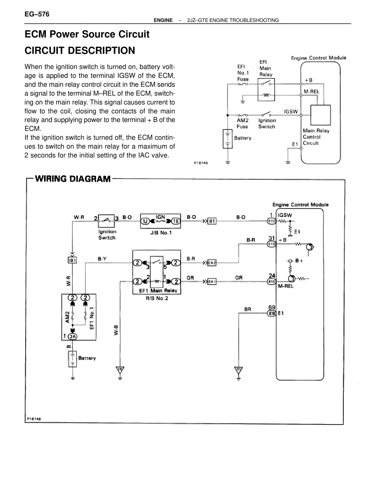
When the ignition switch is turned on, battery volt-age is applied to the terminal IGSW of the ECM, and the main relay control circuit in the ECM sends a signal to the terminal M–REL of the ECM, switch-ing on the main relay. This signal causes current to flow to the coil, closing the contacts of the main relay and supplying power to the terminal + B of the ECM.
If the ignition switch is turned off, the ECM contin-ues to switch on the main relay for a maximum of 2 seconds for the initial setting of the IAC valve.
Engine Control Module
EFI
No.1
Fuse
EFI
Main
Relay
+B
M-REL
IGSW
AM2
Fuse
Ignition
Switch
Main Relay
Control
Circuit
Battery
E1
P18745
WIRING DIAGRAM
Engine Control Module
W-R 2 3 B-O
Ignition
Switch
1J 1E IGN
J/B No.1
B-O
II1
B-O 1 IGSW
E18
E1
B-R 31 +B
E10
IB1
B-Y
2 2
3
5
B-R
EA2
B+
W-R
2 2
1
GR
EA1
GR 24
E10
M-REL
EF1 Main Relay
R/B No.2
2 2
AM2
EF1 No.1
2A
B
Battery
W-B
BR 69
E9 E1
P18746