BASIC SUBASSEMBLY SEPARATION
Assembly is in the reverse order of separation.
1. REMOVE BACK–UP LIGHT SWITCH
Torque: 40 N·m (410 kgf·cm, 30 ft·lbf)
2. REMOVE VEHICLE SPEED SENSOR DRIVEN GEAR
Torque: 13 N·m (130 kgf·cm, 9 ft·lbf)
3. REMOVE CLUTCH HOUSING FROM TRANSMISSION CASE
Remove the 9 bolts and clutch housing from the transmission case.
Torque: 37 N·m (380 kgf·cm, 27 ft·lbf)
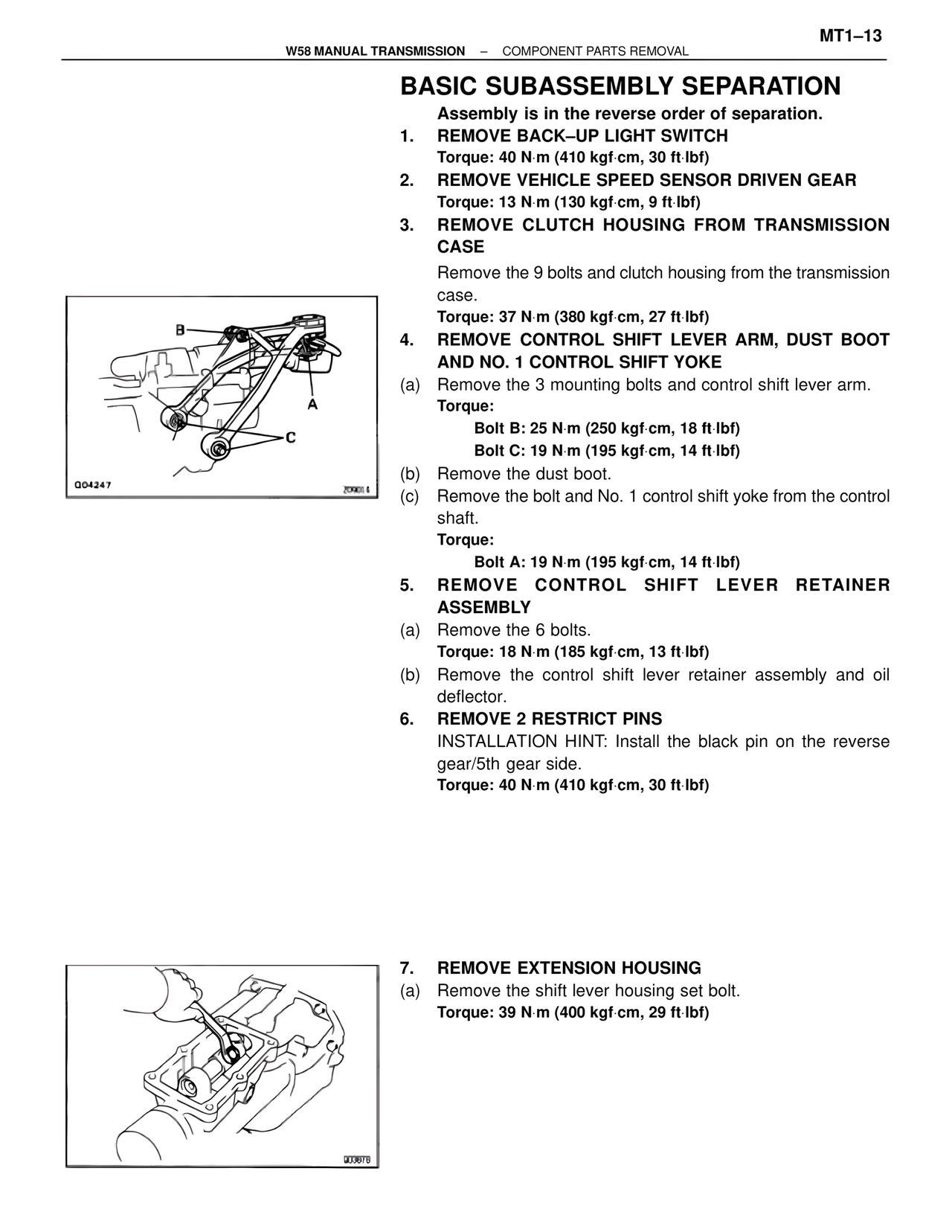
4. REMOVE CONTROL SHIFT LEVER ARM, DUST BOOT AND NO. 1 CONTROL SHIFT YOKE
(a) Remove the 3 mounting bolts and control shift lever arm.
Torque:
Bolt B: 25 N·m (250 kgf·cm, 18 ft·lbf)
Bolt C: 19 N·m (195 kgf·cm, 14 ft·lbf)
(b) Remove the dust boot.
(c) Remove the bolt and No. 1 control shift yoke from the control shaft.
Torque:
Bolt A: 19 N·m (195 kgf·cm, 14 ft·lbf)
5. REMOVE CONTROL SHIFT LEVER RETAINER ASSEMBLY
(a) Remove the 6 bolts.
Torque: 18 N·m (185 kgf·cm, 13 ft·lbf)
(b) Remove the control shift lever retainer assembly and oil deflector.
6. REMOVE 2 RESTRICT PINS
INSTALLATION HINT: Install the black pin on the reverse gear/5th gear side.
Torque: 40 N·m (410 kgf·cm, 30 ft·lbf)
B
A
C
Q04247
Z09014
7. REMOVE EXTENSION HOUSING
(a) Remove the shift lever housing set bolt.
Torque: 39 N·m (400 kgf·cm, 29 ft·lbf)
O03678