POWER SOURCE (Current Flow Chart)
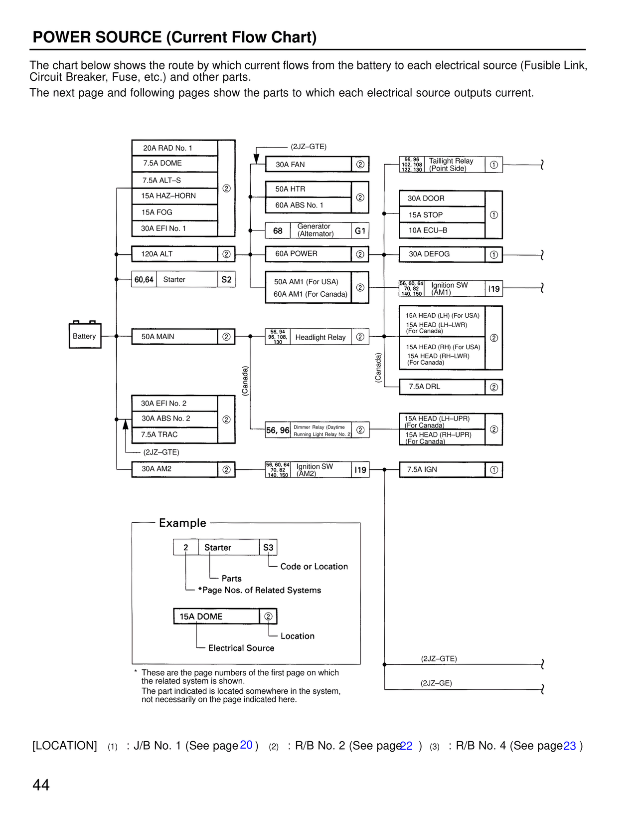
The chart below shows the route by which current flows from the battery to each electrical source (Fusible Link,
Circuit Breaker, Fuse, etc.) and other parts.
The next page and following pages show the parts to which each electrical source outputs current.
20A RAD No. 1
7.5A DOME
7.5A ALT–S
15A HAZ–HORN
15A FOG
30A EFI No. 1
(2JZ–GTE)
30A FAN 2
50A HTR
60A ABS No. 1 2
68 Generator (Alternator) G1
60A POWER 2
50A AM1 (For USA)
60A AM1 (For Canada) 2
56, 96 Taillight Relay (Point Side) 1
102, 108,
122, 130
30A DOOR
15A STOP 1
10A ECU–B
30A DEFOG 1
56, 60, 64 Ignition SW (AM1) I19
140, 150
15A HEAD (LH) (For USA)
15A HEAD (LH–LWR) (For Canada)
15A HEAD (RH) (For USA)
15A HEAD (RH–LWR) (For Canada) 2
7.5A DRL 2
15A HEAD (LH–UPR) (For Canada)
15A HEAD (RH–UPR) (For Canada) 2
120A ALT 2
60, 64 Starter S2
Battery
50A MAIN 2
56, 94
96, 108, Headlight Relay 2
130
(Canada)
30A EFI No. 2
30A ABS No. 2 2
7.5A TRAC
(2JZ–GTE)
56, 96 Dimmer Relay (Daytime Running Light Relay No. 2) 2
(Canada)
30A AM2 2
56, 60, 64 Ignition SW (AM2) I19
70, 82,
140, 150
7.5A IGN 1
— Example —
2 Starter S3
Code or Location
Parts
*Page Nos. of Related Systems
15A DOME 2
Location
Electrical Source
* These are the page numbers of the first page on which
the related system is shown.
The part indicated is located somewhere in the system,
not necessarily on the page indicated here.
(2JZ–GTE)
(2JZ–GE)
[LOCATION] (1) : J/B No. 1 (See page 20) (2) : R/B No. 2 (See page 22) (3) : R/B No. 4 (See page 23)
44