AC–8
AIR CONDITIONING SYSTEM – DESCRIPTION
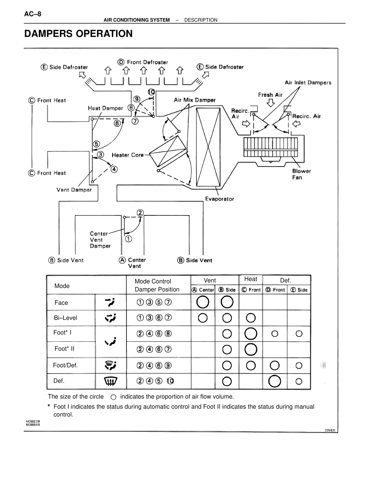
DAMPERS OPERATION
E Side Defroster
D Front Defroster
E Side Defroster
Air Inlet Dampers
Fresh Air
C Front Heat
Heat Damper
Air Mix Damper
Recirc. Air
Recirc. Air
8
10
8
6
7
5
3
Heater Core
4
Blower Fan
C Front Heat
Vent Damper
Evaporator
2
Center Vent Damper
1
B Side Vent
A Center Vent
B Side Vent
Mode | Mode Control Damper Position | Vent A Center | Vent B Side | Heat C Front | Def. D Front | Def. E Side
Face | 1 3 5 7 | O | O | | |
Bi–Level | 1 3 6 7 | O | O | O | |
Foot* I | 2 4 6 8 | | O | O | O | O
Foot* II | 2 4 6 7 | | O | O | |
Foot/Def. | 2 4 6 9 | | O | O | O | O
Def. | 2 4 5 10 | | O | | O | O
The size of the circle O indicates the proportion of air flow volume.
* Foot I indicates the status during automatic control and Foot II indicates the status during manual control.
N08539
N08540
Z09409