Pattern Select Switch Circuit
CIRCUIT DESCRIPTION
The ECM memory contains the shift programs for the NORMAL and MANUAL patterns, 2 position, and L position and the lock–up patterns. Following the programs corresponding to the signals from the pattern select switch, the park/neutral position switch and other various sensors the ECM switches the solenoid valves ON and OFF, thereby controlling the transmission gear change and the lock–up clutch operation.
WIRING DIAGRAM
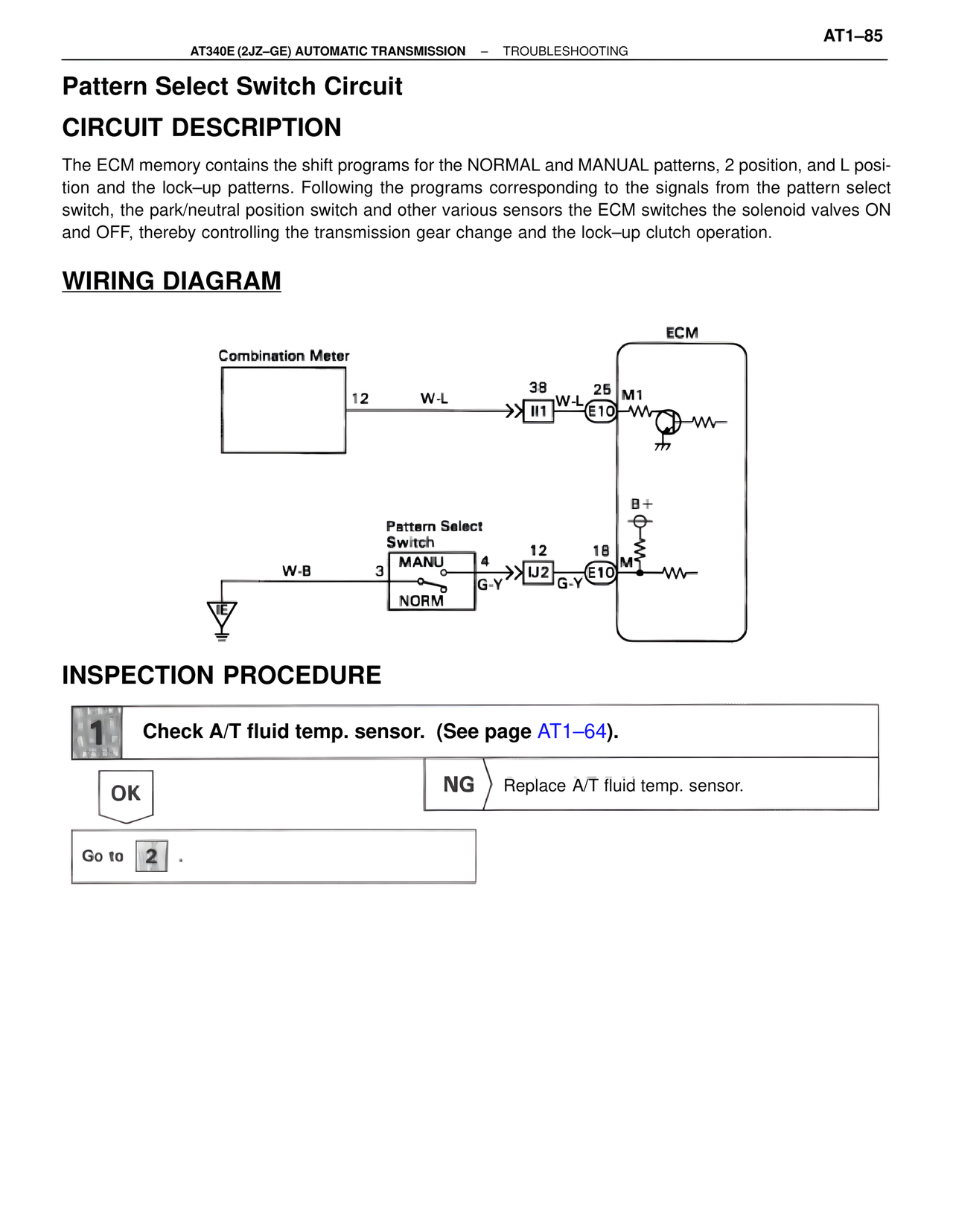
Combination Meter
12 W-L 38 25 M1
II1 W-L E10
ECM
B+
Pattern Select
Switch
W-B 3 MANU 4 12 18
IJ2 G-Y E10 M
NORM
G-Y
IE
INSPECTION PROCEDURE
1 Check A/T fluid temp. sensor. (See page AT1–64).
OK NG Replace A/T fluid temp. sensor.
Go to 2 .