AT2–36
A340E (2JZ—GTE) AUTOMATIC TRANSMISSION – TROUBLESHOOTING
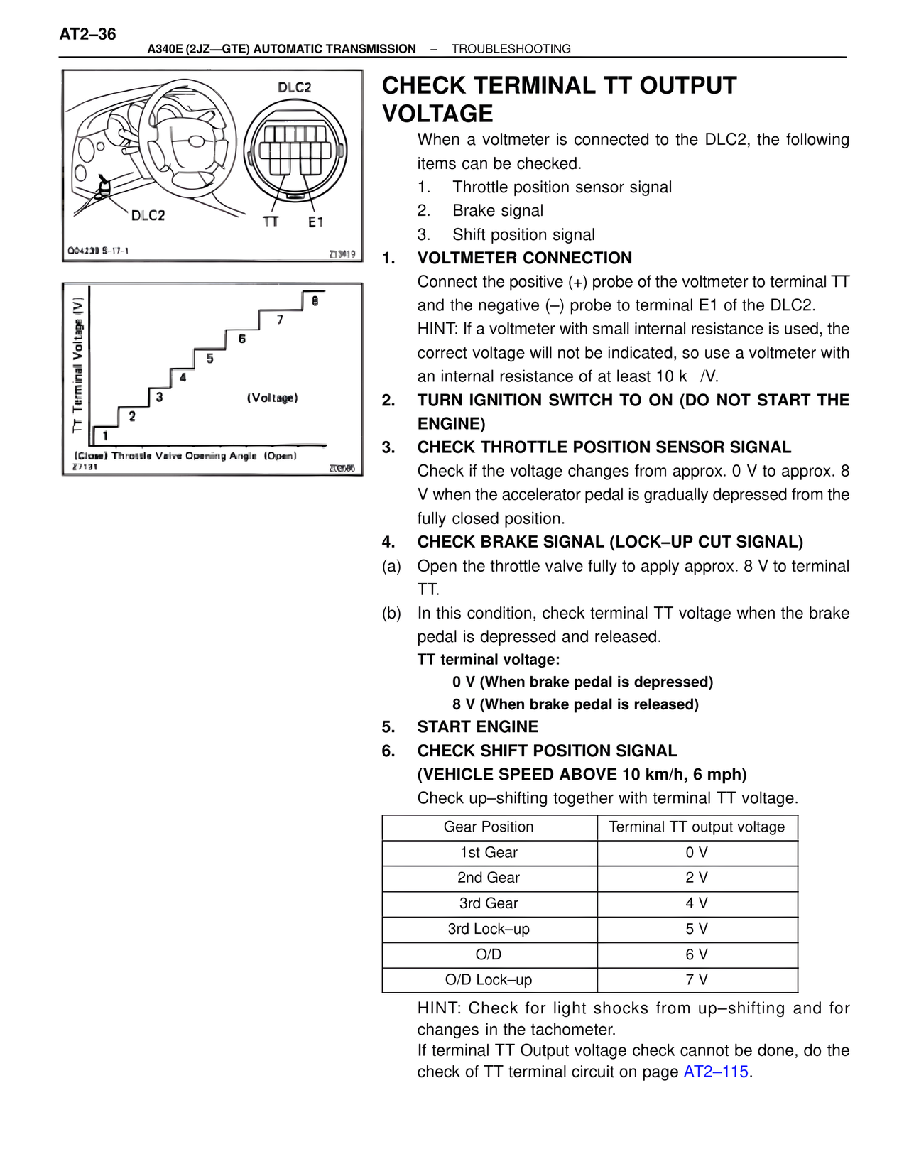
DLC2
DLC2
TT E1
Q04239 S-17-1
Z13419
TT Terminal Voltage (V)
8
7
6
5
4
3
2
1
(Voltage)
(Close) Throttle Valve Opening Angle (Open)
Z7131
Z00566
CHECK TERMINAL TT OUTPUT VOLTAGE
When a voltmeter is connected to the DLC2, the following items can be checked.
1. Throttle position sensor signal
2. Brake signal
3. Shift position signal
1. VOLTMETER CONNECTION
Connect the positive (+) probe of the voltmeter to terminal TT and the negative (–) probe to terminal E1 of the DLC2.
HINT: If a voltmeter with small internal resistance is used, the correct voltage will not be indicated, so use a voltmeter with an internal resistance of at least 10 k /V.
2. TURN IGNITION SWITCH TO ON (DO NOT START THE ENGINE)
3. CHECK THROTTLE POSITION SENSOR SIGNAL
Check if the voltage changes from approx. 0 V to approx. 8 V when the accelerator pedal is gradually depressed from the fully closed position.
4. CHECK BRAKE SIGNAL (LOCK–UP CUT SIGNAL)
(a) Open the throttle valve fully to apply approx. 8 V to terminal TT.
(b) In this condition, check terminal TT voltage when the brake pedal is depressed and released.
TT terminal voltage:
0 V (When brake pedal is depressed)
8 V (When brake pedal is released)
5. START ENGINE
6. CHECK SHIFT POSITION SIGNAL
(VEHICLE SPEED ABOVE 10 km/h, 6 mph)
Check up–shifting together with terminal TT voltage.
Gear Position | Terminal TT output voltage
1st Gear | 0 V
2nd Gear | 2 V
3rd Gear | 4 V
3rd Lock–up | 5 V
O/D | 6 V
O/D Lock–up | 7 V
HINT: Check for light shocks from up–shifting and for changes in the tachometer.
If terminal TT Output voltage check cannot be done, do the check of TT terminal circuit on page AT2–115.