AT2–75
A340E (2JZ—GTE) AUTOMATIC TRANSMISSION – TROUBLESHOOTING
DTC 46 No.4 Solenoid Valve Circuit (For Accumulator Back Pressure Modulation)
CIRCUIT DESCRIPTION
The No.4 solenoid valve controls the hydraulic pressure acting on
the brakes and clutches of the planetary gear units when gears are
shifted and performs smooth gear shifting.
The ECM determines optimum operating pressure according to
the signals from the throttle position sensor, vehicle speed sensor
and O/D clutch speed sensor and controls the volume of current
flow to the solenoid valve.
The amount of electric current to the solenoid is controlled by the
(*) duty ratio of ECM output signals, causing momentary change
to the hydraulic pressure acting on the clutches during gear shift-
ing. When the duty ratio is high, the hydraulic pressure acting on
the clutches is now.
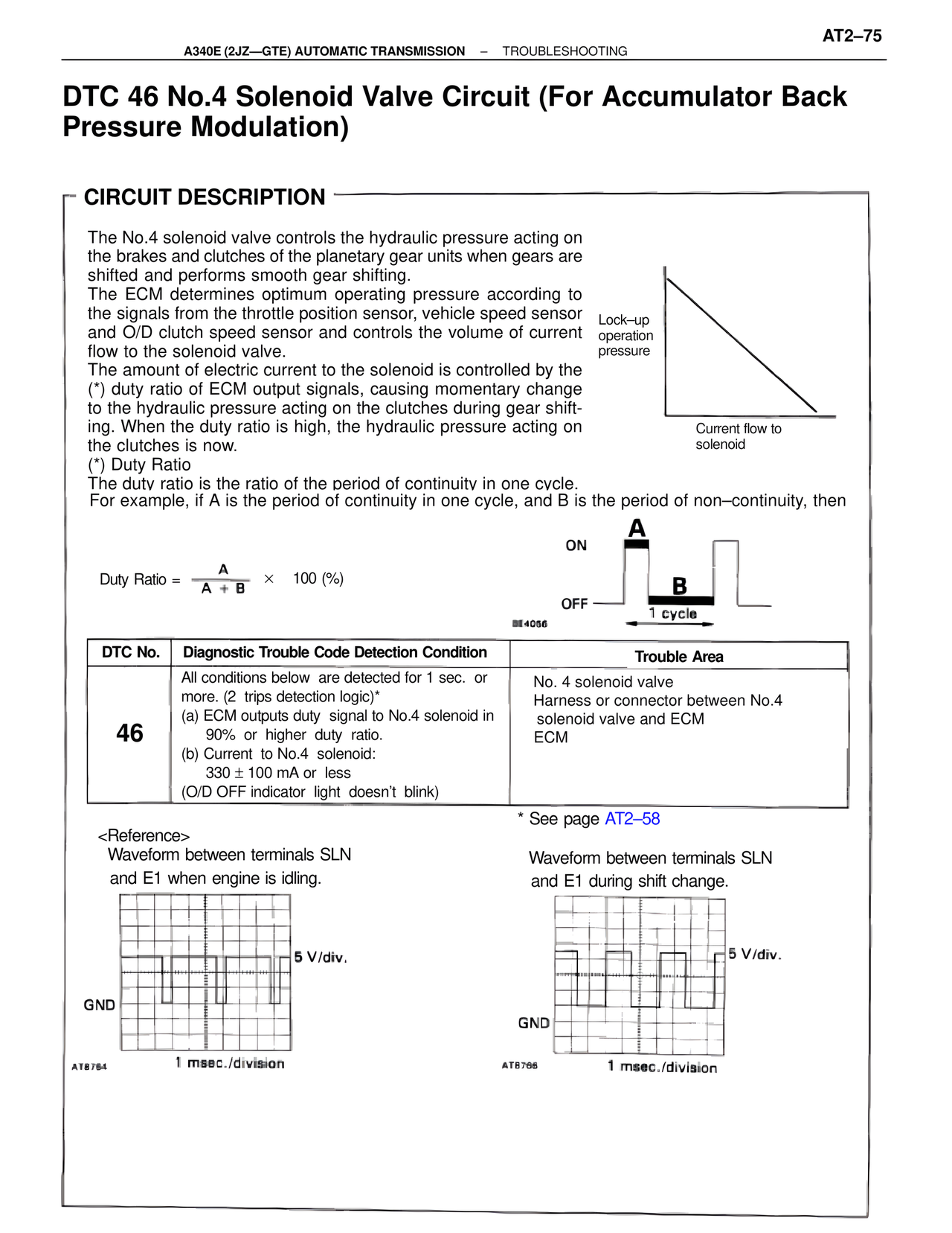
(*) Duty Ratio
The duty ratio is the ratio of the period of continuity in one cycle.
For example, if A is the period of continuity in one cycle, and B is the period of non–continuity, then
Duty Ratio = A / (A + B) × 100 (%)
ON
A
B
OFF
1 cycle
BE4056
Lock–up
operation
pressure
Current flow to
solenoid
DTC No. | Diagnostic Trouble Code Detection Condition | Trouble Area
46 | All conditions below are detected for 1 sec. or
more. (2 trips detection logic)*
(a) ECM outputs duty signal to No.4 solenoid in
90% or higher duty ratio.
(b) Current to No.4 solenoid:
330 ± 100 mA or less
(O/D OFF indicator light doesn't blink) | No. 4 solenoid valve
Harness or connector between No.4
solenoid valve and ECM
ECM
* See page AT2–58
<Reference>
Waveform between terminals SLN
and E1 when engine is idling.
AT8764
5 V/div.
GND
1 msec./division
Waveform between terminals SLN
and E1 during shift change.
AT8766
5 V/div.
GND
1 msec./division