BR–13
BRAKE SYSTEM – MASTER CYLINDER
MASTER CYLINDER DISASSEMBLY
Assembly is in the reverse order of disassembly.
ASSEMBLY NOTICE: Apply lithium soap base glycol
grease to the rubber parts indicated by the arrows (See
page BR–12).
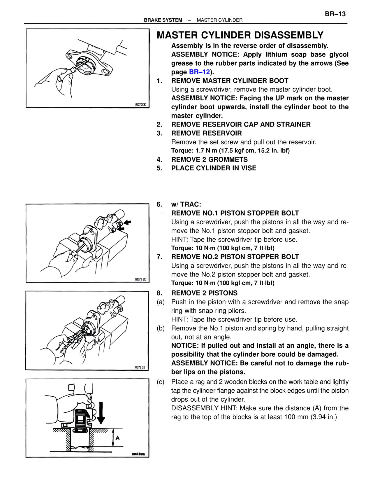
1. REMOVE MASTER CYLINDER BOOT
Using a screwdriver, remove the master cylinder boot.
ASSEMBLY NOTICE: Facing the UP mark on the master
cylinder boot upwards, install the cylinder boot to the
master cylinder.
2. REMOVE RESERVOIR CAP AND STRAINER
3. REMOVE RESERVOIR
Remove the set screw and pull out the reservoir.
Torque: 1.7 N·m (17.5 kgf·cm, 15.2 in.·lbf)
4. REMOVE 2 GROMMETS
5. PLACE CYLINDER IN VISE
R07200
6. w/ TRAC:
REMOVE NO.1 PISTON STOPPER BOLT
Using a screwdriver, push the pistons in all the way and re-
move the No.1 piston stopper bolt and gasket.
HINT: Tape the screwdriver tip before use.
Torque: 10 N·m (100 kgf·cm, 7 ft·lbf)
7. REMOVE NO.2 PISTON STOPPER BOLT
Using a screwdriver, push the pistons in all the way and re-
move the No.2 piston stopper bolt and gasket.
Torque: 10 N·m (100 kgf·cm, 7 ft·lbf)
R07120
8. REMOVE 2 PISTONS
(a) Push in the piston with a screwdriver and remove the snap
ring with snap ring pliers.
HINT: Tape the screwdriver tip before use.
(b) Remove the No.1 piston and spring by hand, pulling straight
out, not at an angle.
NOTICE: If pulled out and install at an angle, there is a
possibility that the cylinder bore could be damaged.
ASSEMBLY NOTICE: Be careful not to damage the rub-
ber lips on the pistons.
(c) Place a rag and 2 wooden blocks on the work table and lightly
tap the cylinder flange against the block edges until the piston
drops out of the cylinder.
DISASSEMBLY HINT: Make sure the distance (A) from the
rag to the top of the blocks is at least 100 mm (3.94 in.)
R07121
BR3895
A