BR–80
BRAKE SYSTEM – ANTI–LOCK BRAKE SYSTEM (ABS)
DTC 17 18 TRAC Motor Relay Circuit
CIRCUIT DESCRIPTION
This relay circuit supplies power to the TRAC pump motor. While the TRAC is activated, the ECU switches the motor relay ON and operates the TRAC pump motor.
DTC No. | Diagnostic Trouble Code Detecting Condition | Trouble area
17
Conditions (1) and (2) continue for 0.2 sec. or more:
(1) TRAC motor relay terminal (TMR) voltage: Battery positive voltage
(2) Voltage of ABS & TRAC ECU terminal MTT: 0 V
TRAC motor relay
Open or short in TRAC motor relay circuit
ECU
18
Conditions (1) and (2) continue for 2 sec. or more:
(1) TRAC motor relay terminal (TMR) voltage: 0 V
(2) Voltage of ABS & TRAC ECU terminal MTT: Battery positive voltage
TRAC motor relay
B+ short in TRAC motor relay circuit
ECU
Fail safe function: If trouble occurs in this relay circuit, the ECU cuts off current to the TRAC solenoid relay and prohibits TRAC control.
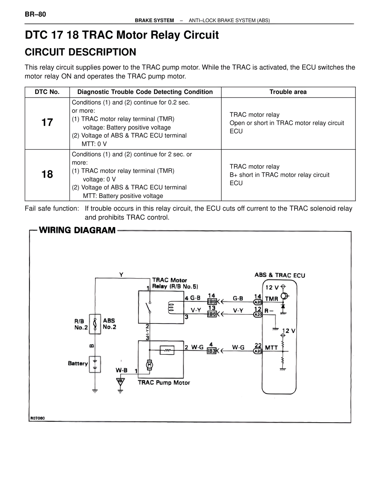
WIRING DIAGRAM
Y
TRAC Motor Relay (R/B No.5)
4 G-B
V-Y
3
R/B No.2
ABS No.2
2
3
2 W-G
Battery
W-B 1
TRAC Pump Motor
ABS & TRAC ECU
12 V
G-B 14 TMR
14
IB6
A20
V-Y 13
12 R-
13
IB6
A20
12 V
W-G 4
22 MTT
IB3
A20
R07060