BR–83
BRAKE SYSTEM – ANTI–LOCK BRAKE SYSTEM (ABS)
DTC 21 22 23 24 ABS Actuator Solenoid Circuit
CIRCUIT DESCRIPTION
This solenoid goes on when signals are received from the ECU and controls the fluid pressure acting on the brake cylinders, thus controlling the braking force.
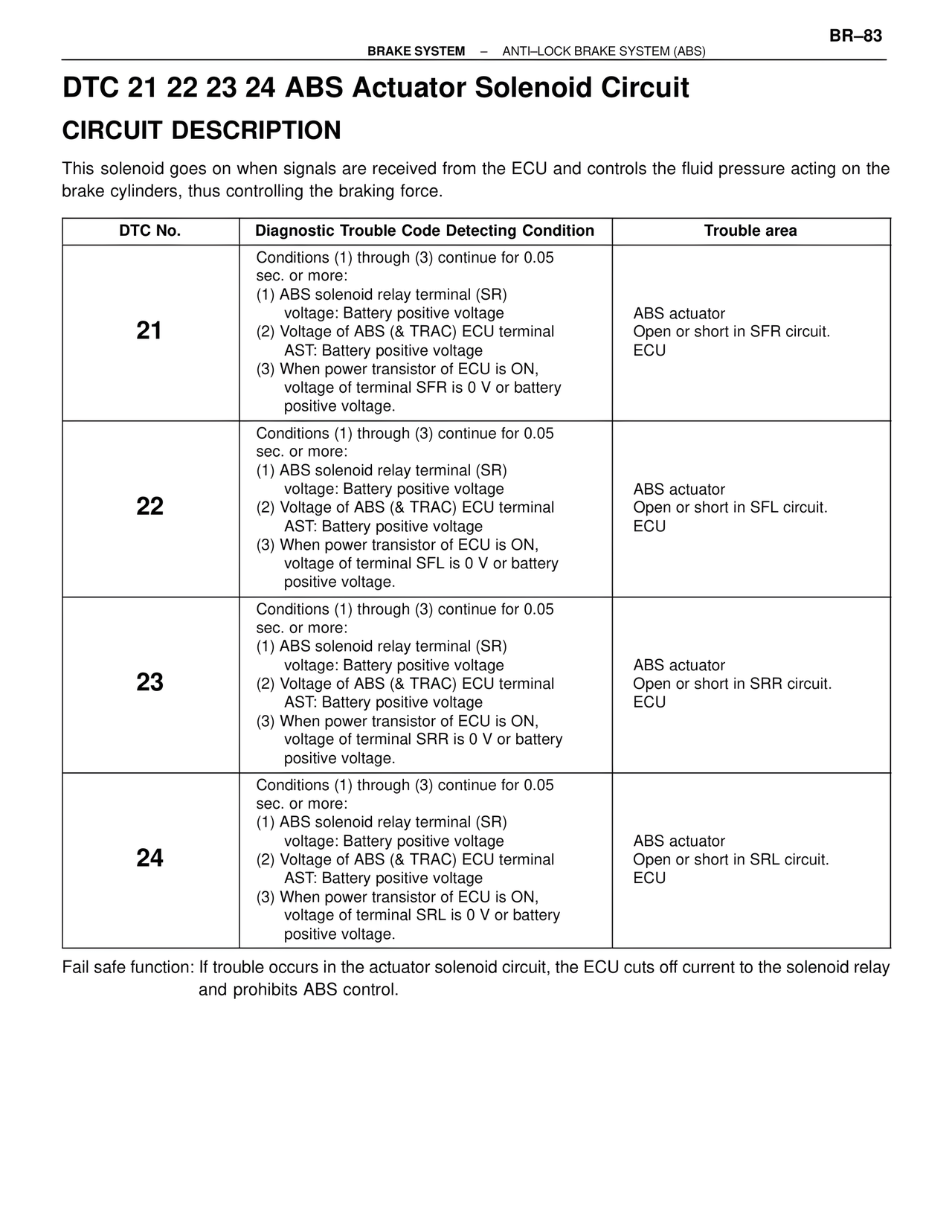
DTC No. | Diagnostic Trouble Code Detecting Condition | Trouble area
21
Conditions (1) through (3) continue for 0.05 sec. or more:
(1) ABS solenoid relay terminal (SR) voltage: Battery positive voltage
(2) Voltage of ABS (& TRAC) ECU terminal AST: Battery positive voltage
(3) When power transistor of ECU is ON, voltage of terminal SFR is 0 V or battery positive voltage.
ABS actuator
Open or short in SFR circuit.
ECU
22
Conditions (1) through (3) continue for 0.05 sec. or more:
(1) ABS solenoid relay terminal (SR) voltage: Battery positive voltage
(2) Voltage of ABS (& TRAC) ECU terminal AST: Battery positive voltage
(3) When power transistor of ECU is ON, voltage of terminal SFL is 0 V or battery positive voltage.
ABS actuator
Open or short in SFL circuit.
ECU
23
Conditions (1) through (3) continue for 0.05 sec. or more:
(1) ABS solenoid relay terminal (SR) voltage: Battery positive voltage
(2) Voltage of ABS (& TRAC) ECU terminal AST: Battery positive voltage
(3) When power transistor of ECU is ON, voltage of terminal SRR is 0 V or battery positive voltage.
ABS actuator
Open or short in SRR circuit.
ECU
24
Conditions (1) through (3) continue for 0.05 sec. or more:
(1) ABS solenoid relay terminal (SR) voltage: Battery positive voltage
(2) Voltage of ABS (& TRAC) ECU terminal AST: Battery positive voltage
(3) When power transistor of ECU is ON, voltage of terminal SRL is 0 V or battery positive voltage.
ABS actuator
Open or short in SRL circuit.
ECU
Fail safe function: If trouble occurs in the actuator solenoid circuit, the ECU cuts off current to the solenoid relay and prohibits ABS control.