BE-135
BODY ELECTRICAL SYSTEM – THEFT DETERRENT AND DOOR LOCK CONTROL SYSTEM
INSPECTION PROCEDURE
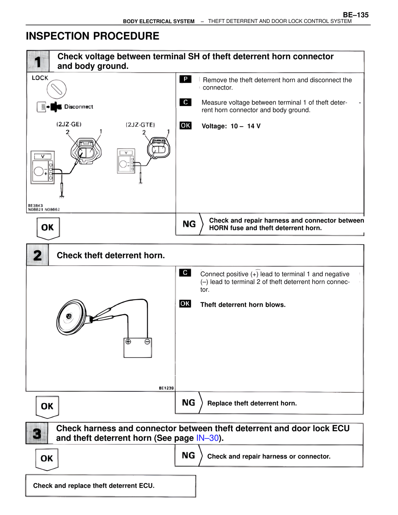
1 Check voltage between terminal SH of theft deterrent horn connector and body ground.
LOCK
Disconnect
(2JZ-GE) (2JZ-GTE)
2 1 2 1
BE3843
N08621 N08662
P Remove the theft deterrent horn and disconnect the connector.
C Measure voltage between terminal 1 of theft deterrent horn connector and body ground.
OK Voltage: 10 – 14 V
OK
NG Check and repair harness and connector between HORN fuse and theft deterrent horn.
2 Check theft deterrent horn.
BE1239
C Connect positive (+) lead to terminal 1 and negative (–) lead to terminal 2 of theft deterrent horn connector.
OK Theft deterrent horn blows.
OK
NG Replace theft deterrent horn.
3 Check harness and connector between theft deterrent and door lock ECU and theft deterrent horn (See page IN–30).
OK
NG Check and repair harness or connector.
Check and replace theft deterrent ECU.