BE–136
BODY ELECTRICAL SYSTEM – THEFT DETERRENT AND DOOR LOCK CONTROL SYSTEM
Headlight Control Relay Circuit
CIRCUIT DESCRIPTION
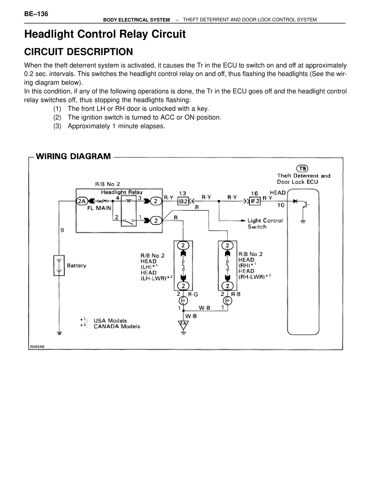
When the theft deterrent system is activated, it causes the Tr in the ECU to switch on and off at approximately 0.2 sec. intervals. This switches the headlight control relay on and off, thus flashing the headlights (See the wiring diagram below).
In this condition, if any of the following operations is done, the Tr in the ECU goes off and the headlight control relay switches off, thus stopping the headlights flashing:
(1) The front LH or RH door is unlocked with a key.
(2) The ignition switch is turned to ACC or ON position.
(3) Approximately 1 minute elapses.
WIRING DIAGRAM
T9
Theft Deterrent and
Door Lock ECU
R/B No.2
Headlight Relay
2A 4 3 2
FL MAIN
2 1 2
R-Y 13
IB2 R-Y R-Y 16 HEAD
IF2 R-Y
10
R
Light Control
Switch
B
2
R/B No.2
HEAD
(LH)*1
HEAD
(LH-LWR)*2
2
R/B No.2
HEAD
(RH)*1
HEAD
(RH-LWR)*2
Battery
2
2
R-G
1 W-B
W-B
EA
2
2
R-B
1
*1: USA Models
*2: CANADA Models
N0854B