BE–140
BODY ELECTRICAL SYSTEM – THEFT DETERRENT AND DOOR LOCK CONTROL SYSTEM
Ignition Switch Circuit
CIRCUIT DESCRIPTION
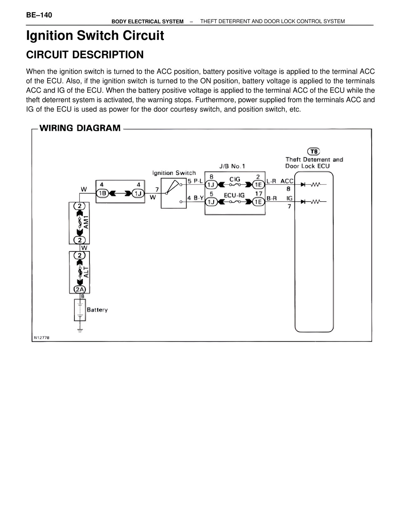
When the ignition switch is turned to the ACC position, battery positive voltage is applied to the terminal ACC
of the ECU. Also, if the ignition switch is turned to the ON position, battery voltage is applied to the terminals
ACC and IG of the ECU. When the battery positive voltage is applied to the terminal ACC of the ECU while the
theft deterrent system is activated, the warning stops. Furthermore, power supplied from the terminals ACC and
IG of the ECU is used as power for the door courtesy switch, and position switch, etc.
WIRING DIAGRAM
Ignition Switch
J/B No.1
T8
Theft Deterrent and
Door Lock ECU
5 P-L
8
2
W
4
4
CIG
L-R ACC
1J
1E
1B
1J
7
8
W
5
17
4 B-Y
ECU-IG
B-R IG
1J
1E
7
2
AM1
2
W
2
ALT
2A
B
Battery
N12778