BE-141
BODY ELECTRICAL SYSTEM — THEFT DETERRENT AND DOOR LOCK CONTROL SYSTEM
INSPECTION PROCEDURE
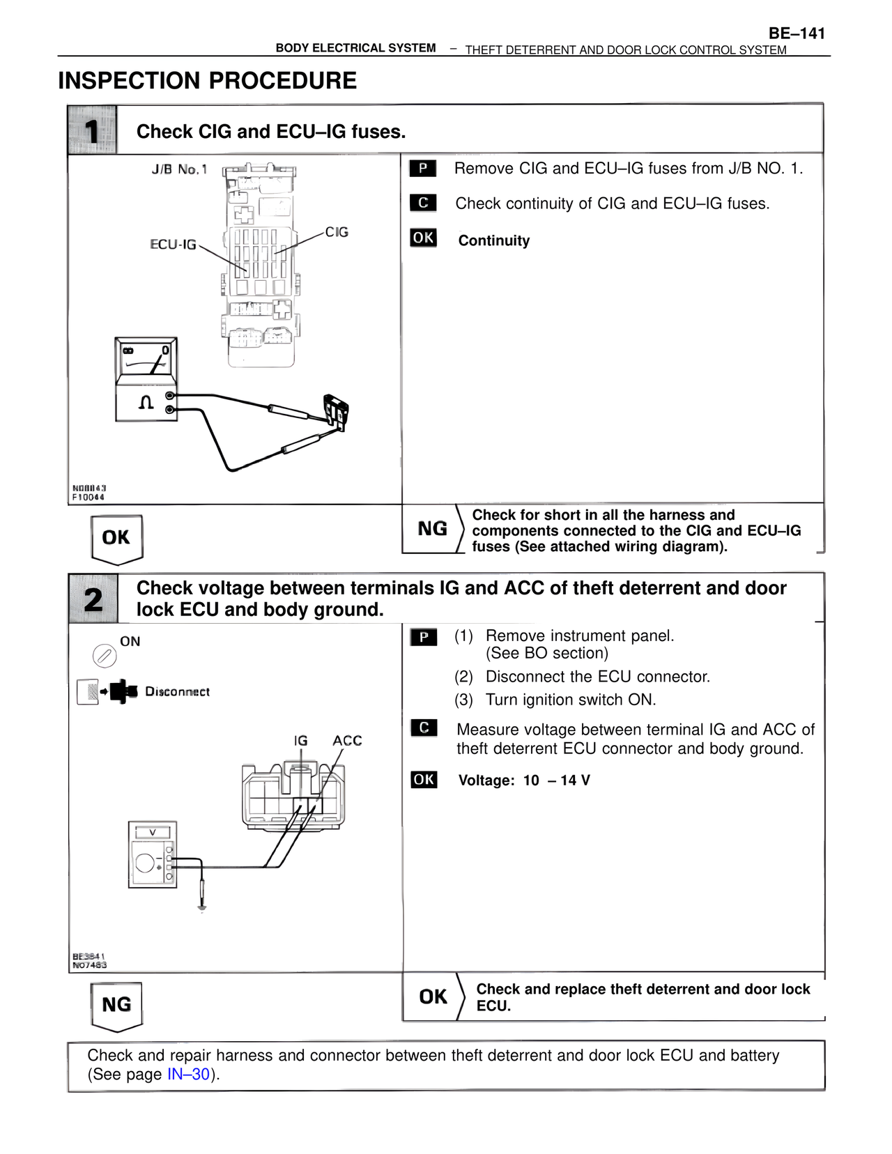
1 Check CIG and ECU–IG fuses.
J/B No. 1
ECU-IG
CIG
N08843
F10044
P Remove CIG and ECU–IG fuses from J/B NO. 1.
C Check continuity of CIG and ECU–IG fuses.
OK Continuity
OK
NG Check for short in all the harness and components connected to the CIG and ECU–IG fuses (See attached wiring diagram).
2 Check voltage between terminals IG and ACC of theft deterrent and door lock ECU and body ground.
ON
Disconnect
IG ACC
BE3841
N07483
P (1) Remove instrument panel.
(See BO section)
(2) Disconnect the ECU connector.
(3) Turn ignition switch ON.
C Measure voltage between terminal IG and ACC of theft deterrent ECU connector and body ground.
OK Voltage: 10 – 14 V
NG
OK Check and replace theft deterrent and door lock ECU.
Check and repair harness and connector between theft deterrent and door lock ECU and battery (See page IN–30).