BE–146
BODY ELECTRICAL SYSTEM – THEFT DETERRENT AND DOOR LOCK CONTROL SYSTEM
INSPECTION PROCEDURE
1 Check door unlock detection switch.
Disconnect
1
3
BE4061
N08681
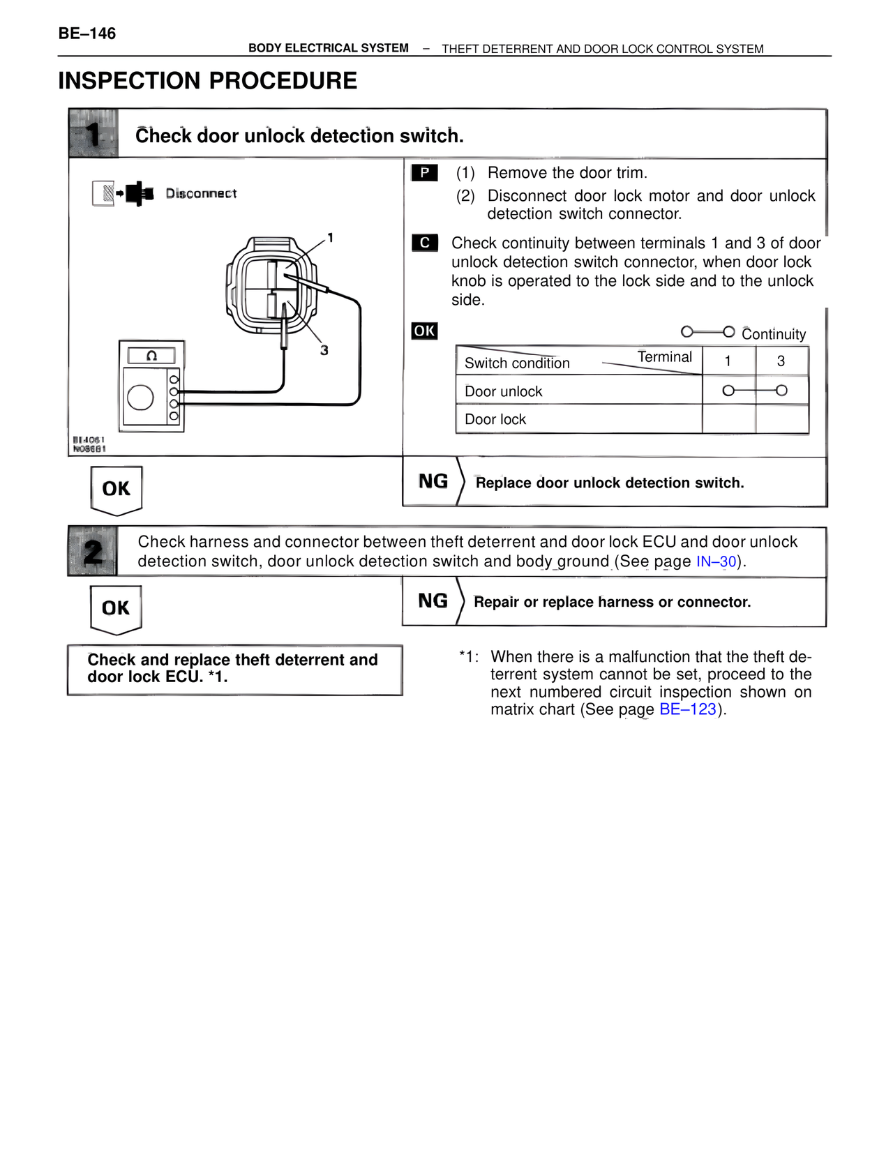
P (1) Remove the door trim.
(2) Disconnect door lock motor and door unlock
detection switch connector.
C Check continuity between terminals 1 and 3 of door
unlock detection switch connector, when door lock
knob is operated to the lock side and to the unlock
side.
OK O——O Continuity
Switch condition Terminal 1 3
Door unlock O O
Door lock
OK
NG Replace door unlock detection switch.
2 Check harness and connector between theft deterrent and door lock ECU and door unlock
detection switch, door unlock detection switch and body ground (See page IN–30).
OK
NG Repair or replace harness or connector.
Check and replace theft deterrent and
door lock ECU. *1.
*1: When there is a malfunction that the theft de-
terrent system cannot be set, proceed to the
next numbered circuit inspection shown on
matrix chart (See page BE–123).