BE-147
BODY ELECTRICAL SYSTEM – THEFT DETERRENT AND DOOR LOCK CONTROL SYSTEM
Door Courtesy Switch Circuit
CIRCUIT DESCRIPTION
The door courtesy switch goes on when the door is opened and goes off when the door is closed.
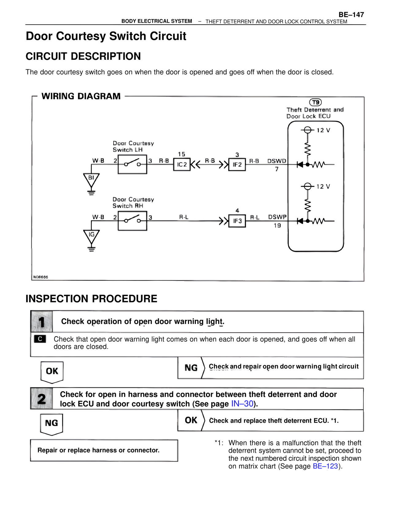
WIRING DIAGRAM
T9
Theft Deterrent and
Door Lock ECU
12 V
Door Courtesy
Switch LH
W-B 2 3 R-B 15 IC2 R-B 3 IF2 R-B DSWD
7
BI
12 V
Door Courtesy
Switch RH
W-B 2 3 R-L 4 IF3 R-L DSWP
19
IG
N06666
INSPECTION PROCEDURE
1 Check operation of open door warning light.
C Check that open door warning light comes on when each door is opened, and goes off when all
doors are closed.
OK NG Check and repair open door warning light circuit
2 Check for open in harness and connector between theft deterrent and door
lock ECU and door courtesy switch (See page IN-30).
NG OK Check and replace theft deterrent ECU. *1.
Repair or replace harness or connector.
*1: When there is a malfunction that the theft
deterrent system cannot be set, proceed to
the next numbered circuit inspection shown
on matrix chart (See page BE-123).