BE–151
BODY ELECTRICAL SYSTEM – THEFT DETERRENT AND DOOR LOCK CONTROL SYSTEM
INSPECTION PROCEDURES
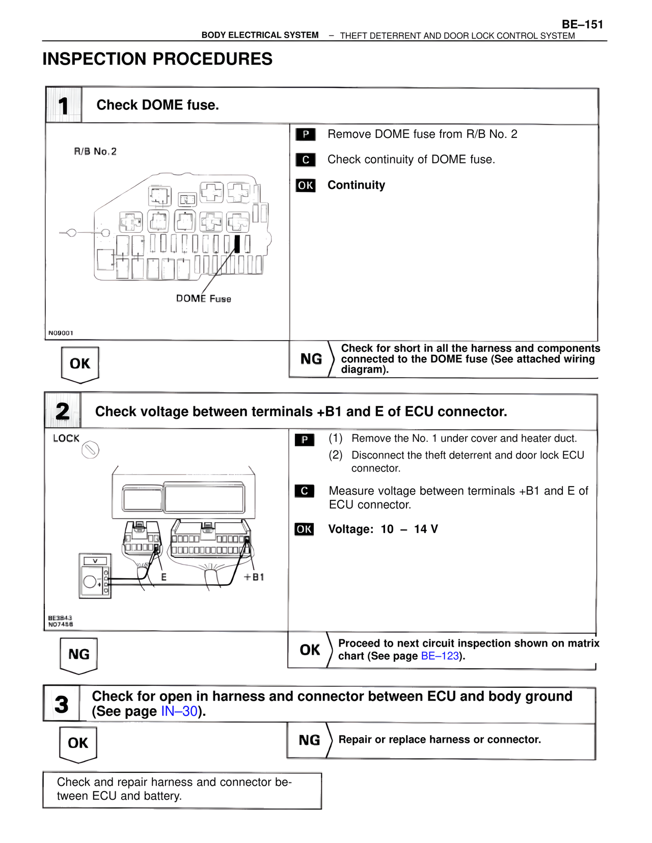
1 Check DOME fuse.
R/B No.2
DOME Fuse
N09001
P Remove DOME fuse from R/B No. 2
C Check continuity of DOME fuse.
OK Continuity
OK
NG Check for short in all the harness and components connected to the DOME fuse (See attached wiring diagram).
2 Check voltage between terminals +B1 and E of ECU connector.
LOCK
E +B1
BE3843
N07458
P (1) Remove the No. 1 under cover and heater duct.
(2) Disconnect the theft deterrent and door lock ECU connector.
C Measure voltage between terminals +B1 and E of ECU connector.
OK Voltage: 10 – 14 V
NG
OK Proceed to next circuit inspection shown on matrix chart (See page BE–123).
3 Check for open in harness and connector between ECU and body ground (See page IN–30).
OK
NG Repair or replace harness or connector.
Check and repair harness and connector between ECU and battery.