BE-157
BODY ELECTRICAL SYSTEM – THEFT DETERRENT AND DOOR LOCK CONTROL SYSTEM
INSPECTION PROCEDURE
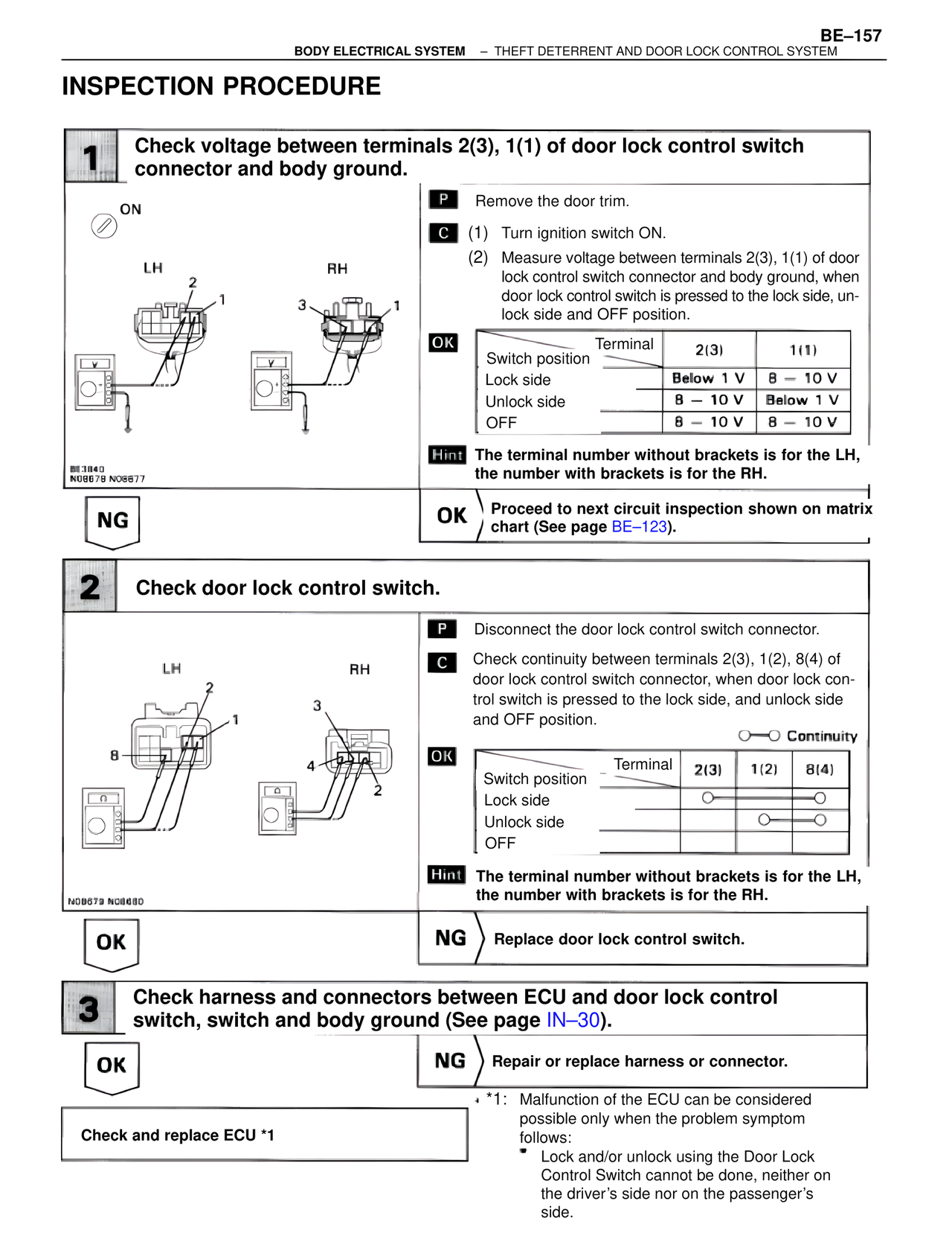
1 Check voltage between terminals 2(3), 1(1) of door lock control switch connector and body ground.
ON
LH RH
BE3840
N09678 N09677
P Remove the door trim.
C (1) Turn ignition switch ON.
(2) Measure voltage between terminals 2(3), 1(1) of door lock control switch connector and body ground, when door lock control switch is pressed to the lock side, unlock side and OFF position.
OK
Switch position Terminal 2(3) 1(1)
Lock side Below 1 V 8 – 10 V
Unlock side 8 – 10 V Below 1 V
OFF 8 – 10 V 8 – 10 V
Hint The terminal number without brackets is for the LH, the number with brackets is for the RH.
NG
OK Proceed to next circuit inspection shown on matrix chart (See page BE-123).
2 Check door lock control switch.
LH RH
N08679 N08680
P Disconnect the door lock control switch connector.
C Check continuity between terminals 2(3), 1(2), 8(4) of door lock control switch connector, when door lock control switch is pressed to the lock side, and unlock side and OFF position.
O—O Continuity
OK
Switch position Terminal 2(3) 1(2) 8(4)
Lock side O O
Unlock side O O
OFF
Hint The terminal number without brackets is for the LH, the number with brackets is for the RH.
OK
NG Replace door lock control switch.
3 Check harness and connectors between ECU and door lock control switch, switch and body ground (See page IN-30).
OK
NG Repair or replace harness or connector.
Check and replace ECU *1
*1: Malfunction of the ECU can be considered possible only when the problem symptom follows:
• Lock and/or unlock using the Door Lock Control Switch cannot be done, neither on the driver's side nor on the passenger's side.