BE–178
BODY ELECTRICAL SYSTEM – CRUISE CONTROL SYSTEM
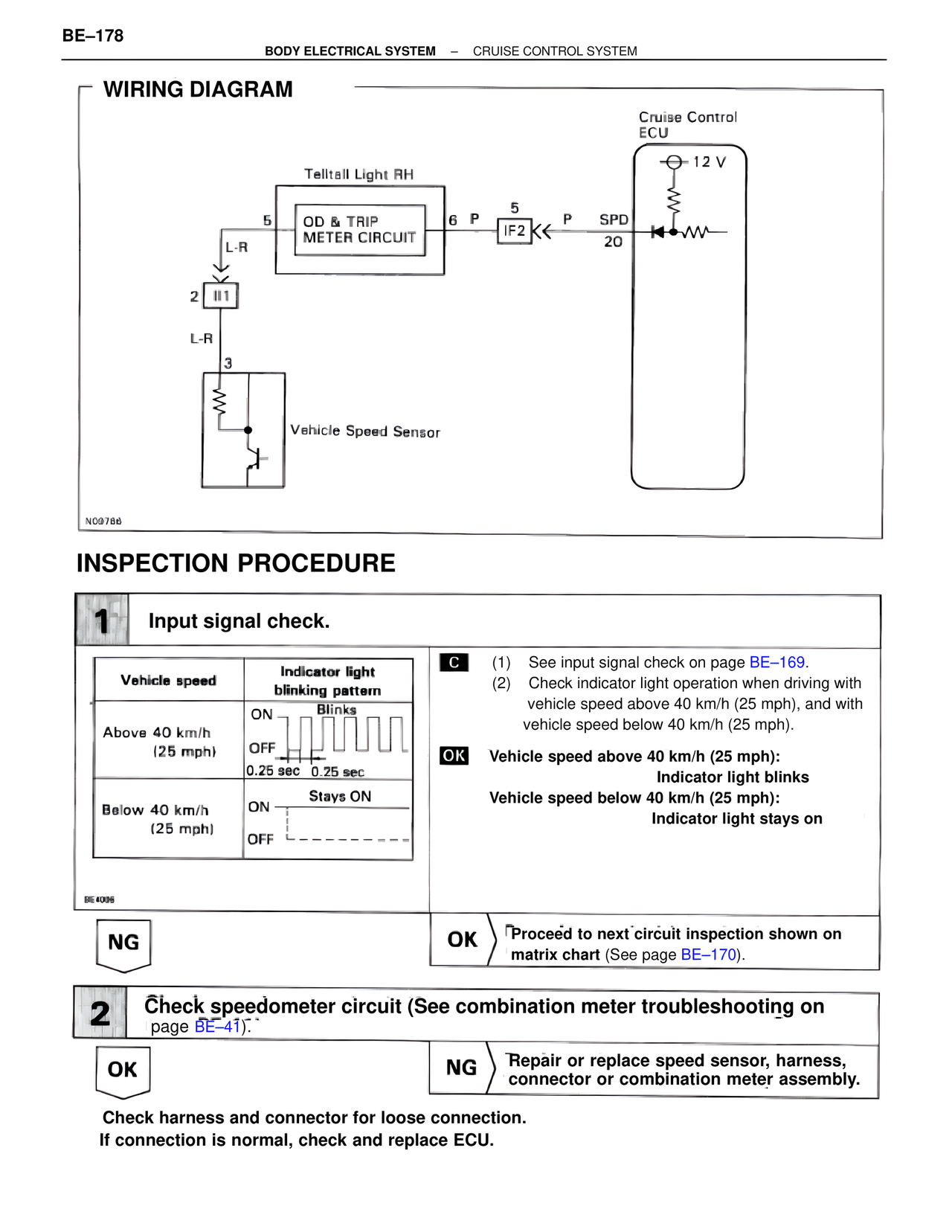
WIRING DIAGRAM
Cruise Control
ECU
⊕ 12 V
Telltail Light RH
5
L-R
OD & TRIP
METER CIRCUIT
6 P
5
IF2 << P SPD
20
2 II1
L-R
3
Vehicle Speed Sensor
NC9786
INSPECTION PROCEDURE
1 Input signal check.
Vehicle speed | Indicator light blinking pattern
Above 40 km/h
(25 mph)
ON Blinks
OFF
0.25 sec 0.25 sec
Below 40 km/h
(25 mph)
ON Stays ON
OFF
BE4006
C (1) See input signal check on page BE–169.
(2) Check indicator light operation when driving with
vehicle speed above 40 km/h (25 mph), and with
vehicle speed below 40 km/h (25 mph).
OK Vehicle speed above 40 km/h (25 mph):
Indicator light blinks
Vehicle speed below 40 km/h (25 mph):
Indicator light stays on
NG OK Proceed to next circuit inspection shown on
matrix chart (See page BE–170).
2 Check speedometer circuit (See combination meter troubleshooting on
page BE–41).
OK NG Repair or replace speed sensor, harness,
connector or combination meter assembly.
Check harness and connector for loose connection.
If connection is normal, check and replace ECU.