BE–18
BODY ELECTRICAL SYSTEM – HEADLIGHT AND TAILLIGHT SYSTEM
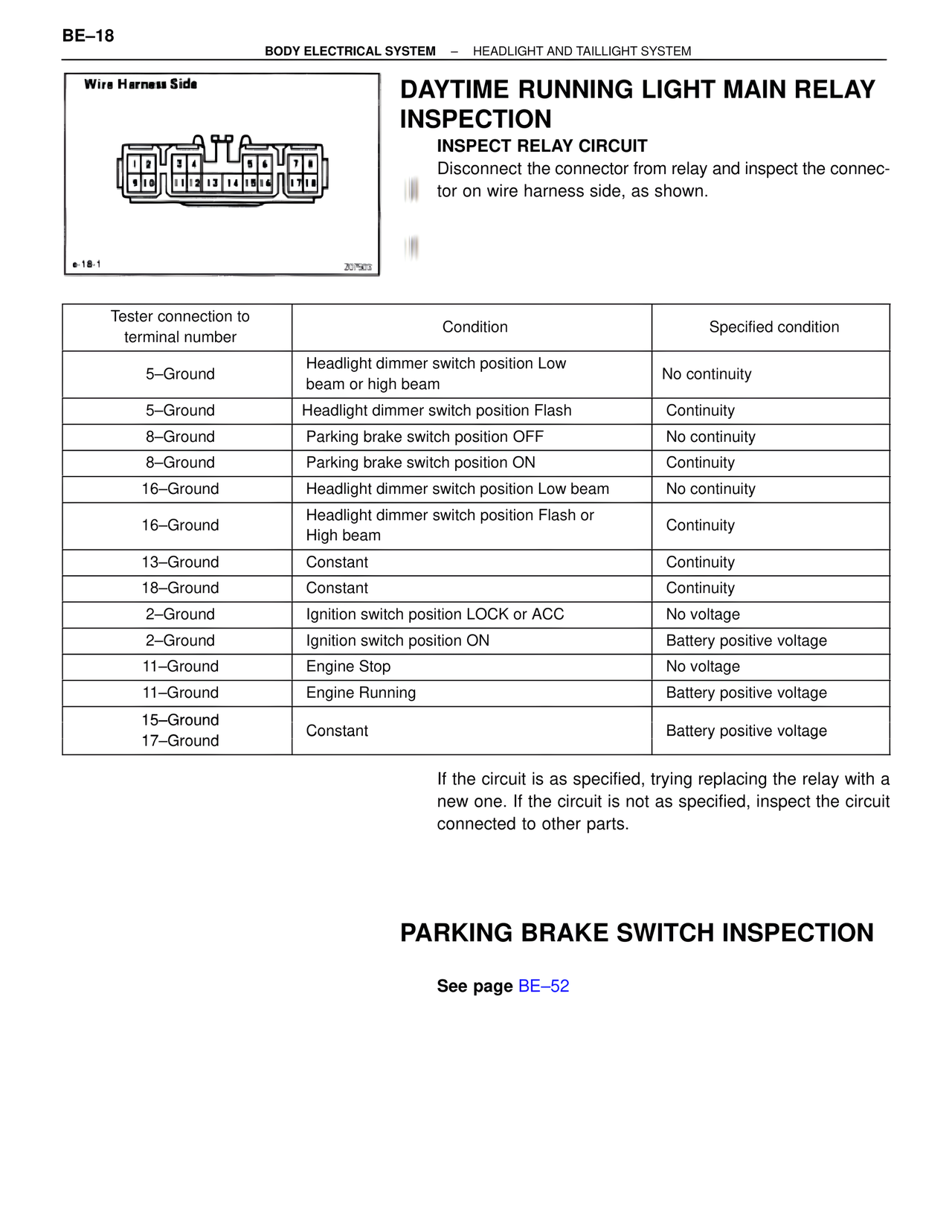
Wire Harness Side
e-18-1
207503
DAYTIME RUNNING LIGHT MAIN RELAY INSPECTION
INSPECT RELAY CIRCUIT
Disconnect the connector from relay and inspect the connector on wire harness side, as shown.
Tester connection to terminal number | Condition | Specified condition
5–Ground | Headlight dimmer switch position Low beam or high beam | No continuity
5–Ground | Headlight dimmer switch position Flash | Continuity
8–Ground | Parking brake switch position OFF | No continuity
8–Ground | Parking brake switch position ON | Continuity
16–Ground | Headlight dimmer switch position Low beam | No continuity
16–Ground | Headlight dimmer switch position Flash or High beam | Continuity
13–Ground | Constant | Continuity
18–Ground | Constant | Continuity
2–Ground | Ignition switch position LOCK or ACC | No voltage
2–Ground | Ignition switch position ON | Battery positive voltage
11–Ground | Engine Stop | No voltage
11–Ground | Engine Running | Battery positive voltage
15–Ground 17–Ground | Constant | Battery positive voltage
If the circuit is as specified, trying replacing the relay with a new one. If the circuit is not as specified, inspect the circuit connected to other parts.
PARKING BRAKE SWITCH INSPECTION
See page BE–52