BODY ELECTRICAL SYSTEM – COMBINATION METER
BE–49
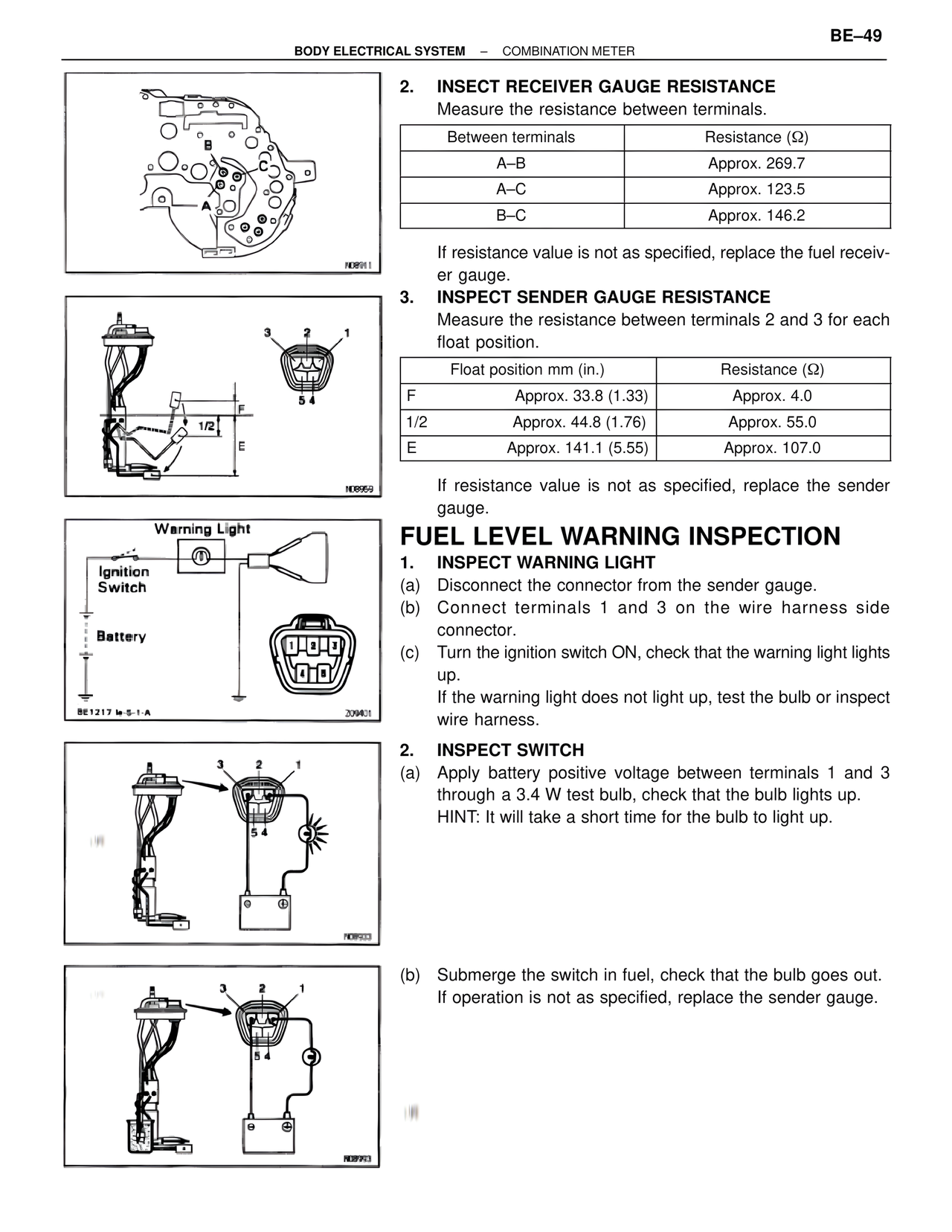
2. INSECT RECEIVER GAUGE RESISTANCE
Measure the resistance between terminals.
Between terminals | Resistance (Ω)
A–B | Approx. 269.7
A–C | Approx. 123.5
B–C | Approx. 146.2
If resistance value is not as specified, replace the fuel receiver gauge.
3. INSPECT SENDER GAUGE RESISTANCE
Measure the resistance between terminals 2 and 3 for each float position.
Float position mm (in.) | Resistance (Ω)
F | Approx. 33.8 (1.33) | Approx. 4.0
1/2 | Approx. 44.8 (1.76) | Approx. 55.0
E | Approx. 141.1 (5.55) | Approx. 107.0
If resistance value is not as specified, replace the sender gauge.
FUEL LEVEL WARNING INSPECTION
1. INSPECT WARNING LIGHT
(a) Disconnect the connector from the sender gauge.
(b) Connect terminals 1 and 3 on the wire harness side connector.
(c) Turn the ignition switch ON, check that the warning light lights up.
If the warning light does not light up, test the bulb or inspect wire harness.
2. INSPECT SWITCH
(a) Apply battery positive voltage between terminals 1 and 3 through a 3.4 W test bulb, check that the bulb lights up.
HINT: It will take a short time for the bulb to light up.
(b) Submerge the switch in fuel, check that the bulb goes out.
If operation is not as specified, replace the sender gauge.
Warning Light
Ignition Switch
Battery
BE1217 M-5-1-A
209401
N08911
N08959
N0P903
N08993