BE–48
BODY ELECTRICAL SYSTEM – COMBINATION METER
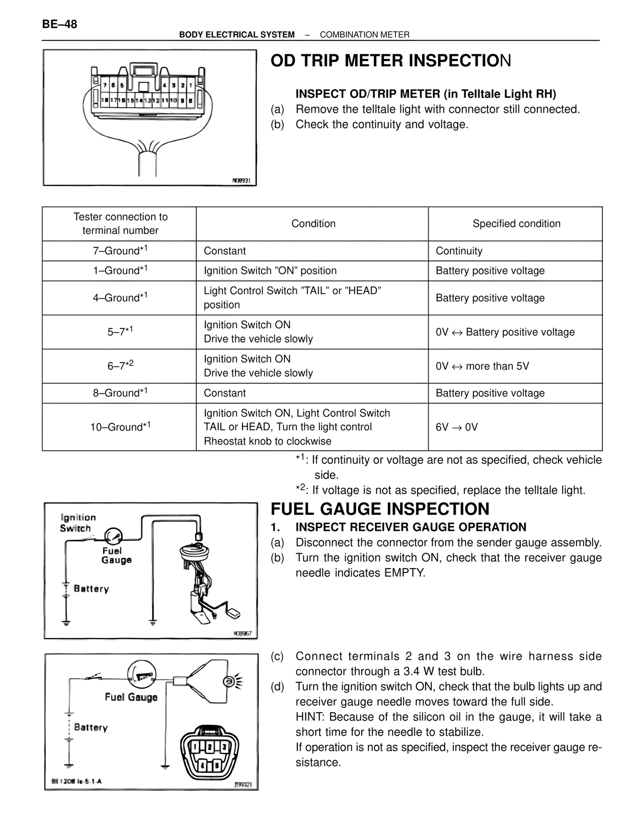
OD TRIP METER INSPECTION
INSPECT OD/TRIP METER (in Telltale Light RH)
(a) Remove the telltale light with connector still connected.
(b) Check the continuity and voltage.
N08931
Tester connection to terminal number | Condition | Specified condition
7–Ground*1 | Constant | Continuity
1–Ground*1 | Ignition Switch "ON" position | Battery positive voltage
4–Ground*1 | Light Control Switch "TAIL" or "HEAD" position | Battery positive voltage
5–7*1 | Ignition Switch ON Drive the vehicle slowly | 0V ↔ Battery positive voltage
6–7*2 | Ignition Switch ON Drive the vehicle slowly | 0V ↔ more than 5V
8–Ground*1 | Constant | Battery positive voltage
10–Ground*1 | Ignition Switch ON, Light Control Switch TAIL or HEAD, Turn the light control Rheostat knob to clockwise | 6V → 0V
*1: If continuity or voltage are not as specified, check vehicle side.
*2: If voltage is not as specified, replace the telltale light.
FUEL GAUGE INSPECTION
Ignition Switch
Fuel Gauge
Battery
H08967
1. INSPECT RECEIVER GAUGE OPERATION
(a) Disconnect the connector from the sender gauge assembly.
(b) Turn the ignition switch ON, check that the receiver gauge needle indicates EMPTY.
Fuel Gauge
Battery
BE1208 Ie-5-1-A
Z09321
(c) Connect terminals 2 and 3 on the wire harness side connector through a 3.4 W test bulb.
(d) Turn the ignition switch ON, check that the bulb lights up and receiver gauge needle moves toward the full side.
HINT: Because of the silicon oil in the gauge, it will take a short time for the needle to stabilize.
If operation is not as specified, inspect the receiver gauge resistance.