EG–102
ENGINE – ENGINE MECHANICAL
Bearing center wall thickness:
Mark "1"
1.492–1.495 mm (0.0587–0.0589 in.)
Mark "2"
1.495–1.498 mm (0.0589–0.0590 in.)
Mark "3"
1.498–1.501 mm (0.0590–0.0591 in.)
Mark "4"
1.501–1.504 mm (0.0591–0.0592 in.)
Mark "5"
1.504–1.507 mm (0.0592–0.0593 in.)
(j) Completely remove the Plastigage.
4. REMOVE PISTON AND CONNECTING ROD ASSEMBLIES
(a) Using a ridge reamer, remove all the carbon from the top of the cylinder.
(b) Push the piston, connecting rod assembly and upper bearing through the top of the cylinder block.
HINT:
• Keep the bearings, connecting rod and cap together.
• Arrange the piston and connecting rod assemblies in correct order.
5. CHECK CRANKSHAFT THRUST CLEARANCE
Using a dial indicator, measure the thrust clearance while prying the crankshaft back and forth with a screwdriver.
Standard thrust clearance:
0.020–0.220 mm (0.0008–0.0087 in.)
Maximum thrust clearance:
0.30 mm (0.0118 in.)
If the thrust clearance is greater than maximum, replace the thrust washers as a set.
Thrust washer thickness:
1.940–1.990 mm (0.0764–0.0783 in.)
6. REMOVE MAIN BEARING CAPS AND CHECK OIL CLEARANCE
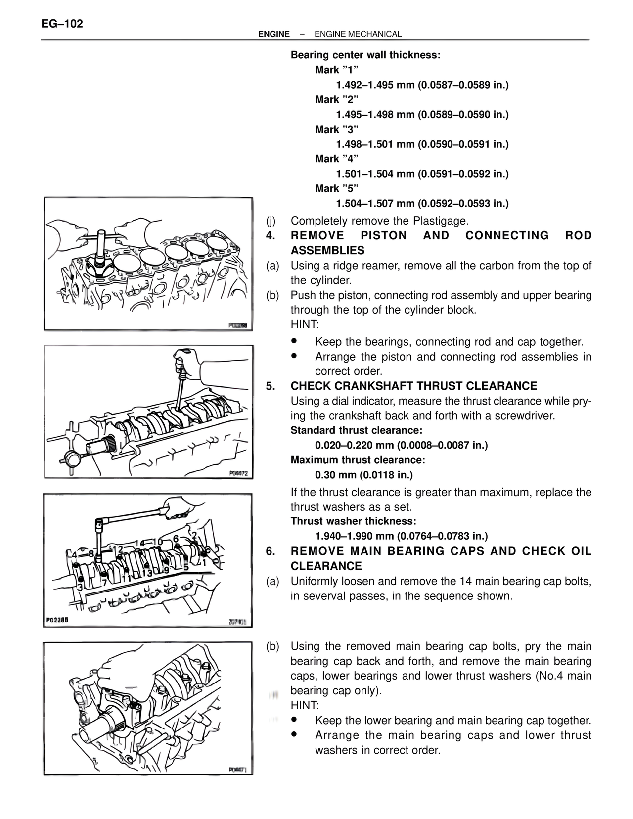
(a) Uniformly loosen and remove the 14 main bearing cap bolts, in severval passes, in the sequence shown.
(b) Using the removed main bearing cap bolts, pry the main bearing cap back and forth, and remove the main bearing caps, lower bearings and lower thrust washers (No.4 main bearing cap only).
HINT:
• Keep the lower bearing and main bearing cap together.
• Arrange the main bearing caps and lower thrust washers in correct order.
P02288
P04472
P02285
Z07401
P04671