EG–12
ENGINE – ENGINE MECHANICAL
Valve clearance (Cold):
Intake
.15–0.25 mm (0.006–0.010 in.)
Exhaust
.25–0.35 mm (0.010–0.014 in.)
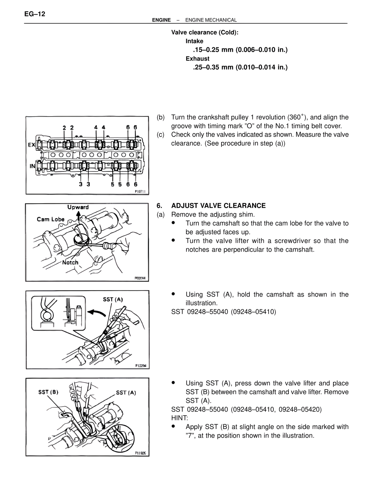
2 2 4 4 6 6
EX
IN
3 3 5 5 6 6
P10711
(b) Turn the crankshaft pulley 1 revolution (360°), and align the
groove with timing mark "O" of the No.1 timing belt cover.
(c) Check only the valves indicated as shown. Measure the valve
clearance. (See procedure in step (a))
Upward
Cam Lobe
Notch
P00094
6. ADJUST VALVE CLEARANCE
(a) Remove the adjusting shim.
• Turn the camshaft so that the cam lobe for the valve to
be adjusted faces up.
• Turn the valve lifter with a screwdriver so that the
notches are perpendicular to the camshaft.
SST (A)
P12204
• Using SST (A), hold the camshaft as shown in the
illustration.
SST 09248–55040 (09248–05410)
SST (B) SST (A)
P11925
• Using SST (A), press down the valve lifter and place
SST (B) between the camshaft and valve lifter. Remove
SST (A).
SST 09248–55040 (09248–05410, 09248–05420)
HINT:
• Apply SST (B) at slight angle on the side marked with
"7", at the position shown in the illustration.