EG–71
ENGINE – ENGINE MECHANICAL
• 6 injectors connectors
HINT: The No.1, No.3 and No.5 injector connectors are dark
gray, and the No.2, No.4 and No.6 injector connectors are
gray.
• 2 camshaft position sensor connectors
• 3 engine wire clamps to injector holders
16. INSTALL AIR INTAKE CHAMBER ASSEMBLY
(See injector installation in SFI System)
17. CONNECT FUEL RETURN HOSE
18. INSTALL PS PUMP
Torque: 58 N·m (590 kgf·cm, 43 ft·lbf)
19. INSTALL WATER OUTLET AND NO.1 WATER BYPASS
PIPE
(a) Install 2 new O–rings to the No.1 water bypass pipe.
(b) Apply soapy water to the O–rings.
(c) Install the No.1 water bypass pipe to the water pump.
(d) Install a new gasket and the water outlet with the 2 bolts.
Torque: 21 N·m (210 kgf·cm, 15 ft·lbf)
(e) Connect the ECT sensor and sender gauge connectors.
(f) Connect the upper radiator hose to the water outlet.
20. INSTALL DRIVE BELT
Install the drive belt by turning the drive belt tensioner clock-
wise.
21. M/T:
INSTALL DRIVE BELT TENSIONER DAMPER
(See step 19 in timing belt installation)
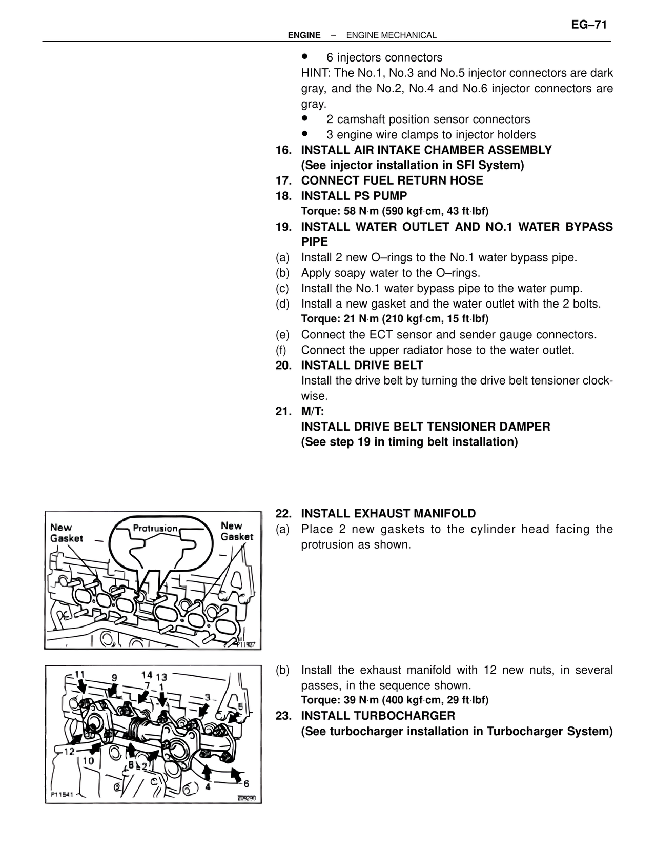
New
Gasket Protrusion New
Gasket
P11927
11 9 14 13
7 1
3
5
-12
10
8 2
4
6
P11541 205290
22. INSTALL EXHAUST MANIFOLD
(a) Place 2 new gaskets to the cylinder head facing the
protrusion as shown.
(b) Install the exhaust manifold with 12 new nuts, in several
passes, in the sequence shown.
Torque: 39 N·m (400 kgf·cm, 29 ft·lbf)
23. INSTALL TURBOCHARGER
(See turbocharger installation in Turbocharger System)