(e) Torque the nut of the tilt No.2 bolt side.
Torque: 15 N·m (150 kgf·cm, 11 ft·lbf)
(f) Torque the nut of the memory bolt side.
Torque: 5.9 N·m (60 kgf·cm, 52 in.·lbf)
(g) Install the spacer and a new E–ring.
13. INSTALL TILT LEVER RIGHT RETAINER
(a) Torque the nut.
Torque: 15 N·m (150 kgf·cm, 11 ft·lbf)
(b) Install a new E–ring.
14. INSTALL TURN SIGNAL BRACKET
(a) Apply sealant to 2 or 3 threads of the 2 bolts.
Sealant:
Part No. 08833–00080, THREE BOND 1344, LOCTITE
242 or equivalent.
(b) Torque the 2 bolts.
Torque: 8.8 N·m (90 kgf·cm, 78 in.·lbf)
15. INSTALL 3 TENSION SPRINGS
16. INSTALL COMPRESSION SPRING
(a) Install the 2 bushings to the spring.
(b) Apply sealant to 2 or 3 threads of the torx screw.
Sealant:
Part No. 08833–00080, THREE BOND 1344, LOCTITE
242 or equivalent.
(c) Using a torx socket wrench, torque the screw.
Torque: 6.4 N·m (65 kgf·cm, 56 in.·lbf)
17. INSTALL COLUMN PROTECTOR AND WIRING HARNESS
CLAMP
Tighten the 2 screws.
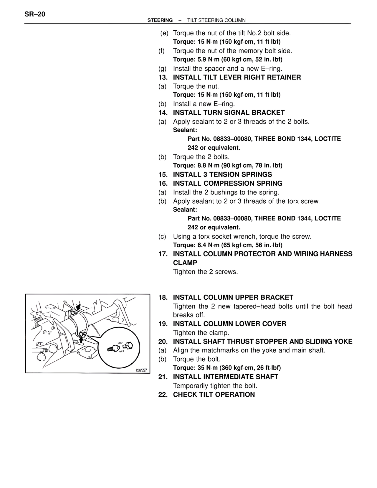
18. INSTALL COLUMN UPPER BRACKET
Tighten the 2 new tapered–head bolts until the bolt head
breaks off.
19. INSTALL COLUMN LOWER COVER
Tighten the clamp.
20. INSTALL SHAFT THRUST STOPPER AND SLIDING YOKE
(a) Align the matchmarks on the yoke and main shaft.
(b) Torque the bolt.
Torque: 35 N·m (360 kgf·cm, 26 ft·lbf)
21. INSTALL INTERMEDIATE SHAFT
Temporarily tighten the bolt.
22. CHECK TILT OPERATION