SR–21
STEERING – TILT STEERING COLUMN
STEERING COLUMN INSTALLATION
1. INSTALL STEERING COLUMN ASSEMBLY
(a) Torque the 4 column assembly set nuts.
Torque: 25 N·m (260 kgf·cm, 19 ft·lbf)
(b) Install the brake pedal return spring.
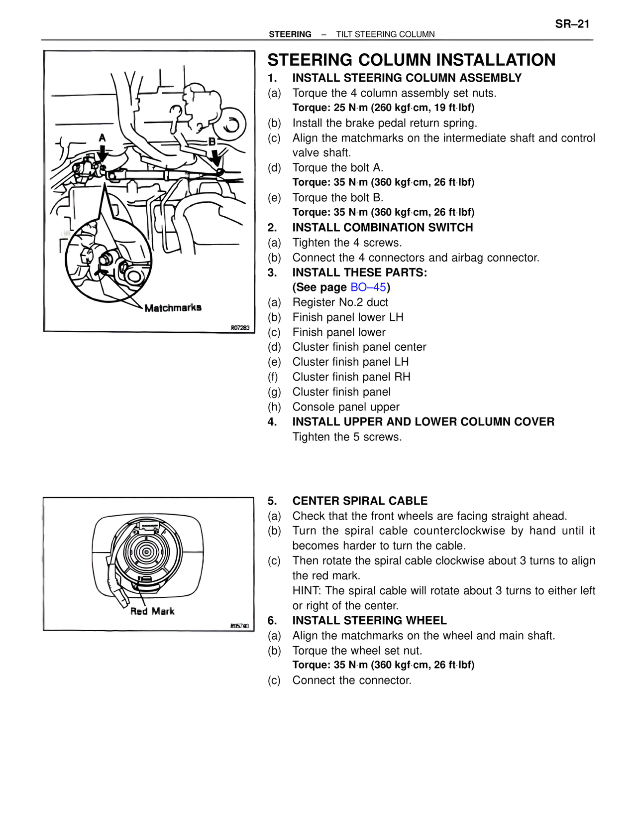
(c) Align the matchmarks on the intermediate shaft and control valve shaft.
(d) Torque the bolt A.
Torque: 35 N·m (360 kgf·cm, 26 ft·lbf)
(e) Torque the bolt B.
Torque: 35 N·m (360 kgf·cm, 26 ft·lbf)
2. INSTALL COMBINATION SWITCH
(a) Tighten the 4 screws.
(b) Connect the 4 connectors and airbag connector.
3. INSTALL THESE PARTS:
(See page BO–45)
(a) Register No.2 duct
(b) Finish panel lower LH
(c) Finish panel lower
(d) Cluster finish panel center
(e) Cluster finish panel LH
(f) Cluster finish panel RH
(g) Cluster finish panel
(h) Console panel upper
4. INSTALL UPPER AND LOWER COLUMN COVER
Tighten the 5 screws.
Matchmarks
R07283
5. CENTER SPIRAL CABLE
(a) Check that the front wheels are facing straight ahead.
(b) Turn the spiral cable counterclockwise by hand until it becomes harder to turn the cable.
(c) Then rotate the spiral cable clockwise about 3 turns to align the red mark.
HINT: The spiral cable will rotate about 3 turns to either left or right of the center.
6. INSTALL STEERING WHEEL
(a) Align the matchmarks on the wheel and main shaft.
(b) Torque the wheel set nut.
Torque: 35 N·m (360 kgf·cm, 26 ft·lbf)
(c) Connect the connector.
Red Mark
R05740