SR–36
STEERING – POWER STEERING GEAR
POWER STEERING GEAR REMOVAL
1. REMOVE ENGINE UNDER COVER
Remove the 10 screws.
2. REMOVE FR SUSPENSION MEMBER PROTECTOR
Remove the 4 bolts.
3. DISCONNECT INTERMEDIATE SHAFT
(See page SR–15)
4. DISCONNECT RH AND LH TIE ROD ENDS
(See page SA–17)
5. DISCONNECT PRESSURE FEED TUBE
Remove the union bolt and gasket.
6. DISCONNECT RETURN TUBE
Remove the union bolt and 2 gaskets.
7. DISCONNECT PPS SOLENOID CONNECTOR
8. REMOVE RACK HOUSING BRACKET AND GROMMET
Remove the 2 bolts and nuts.
9. REMOVE POWER STEERING GEAR ASSEMBLY
Remove the 2 bolts and nuts.
POWER STEERING GEAR DISASSEMBLY
NOTICE: When using a vise, do not overtighten it.
1. SECURE PS GEAR ASSEMBLY IN VISE
Using SST, secure the gear assembly in a vise.
SST 09612–00012
2. REMOVE TURN PRESSURE TUBES
(a) Remove the 2 union bolts and 4 gaskets.
(b) Using SST, remove the 2 tubes.
SST 09633–00020
(c) Remove the 2 union seats.
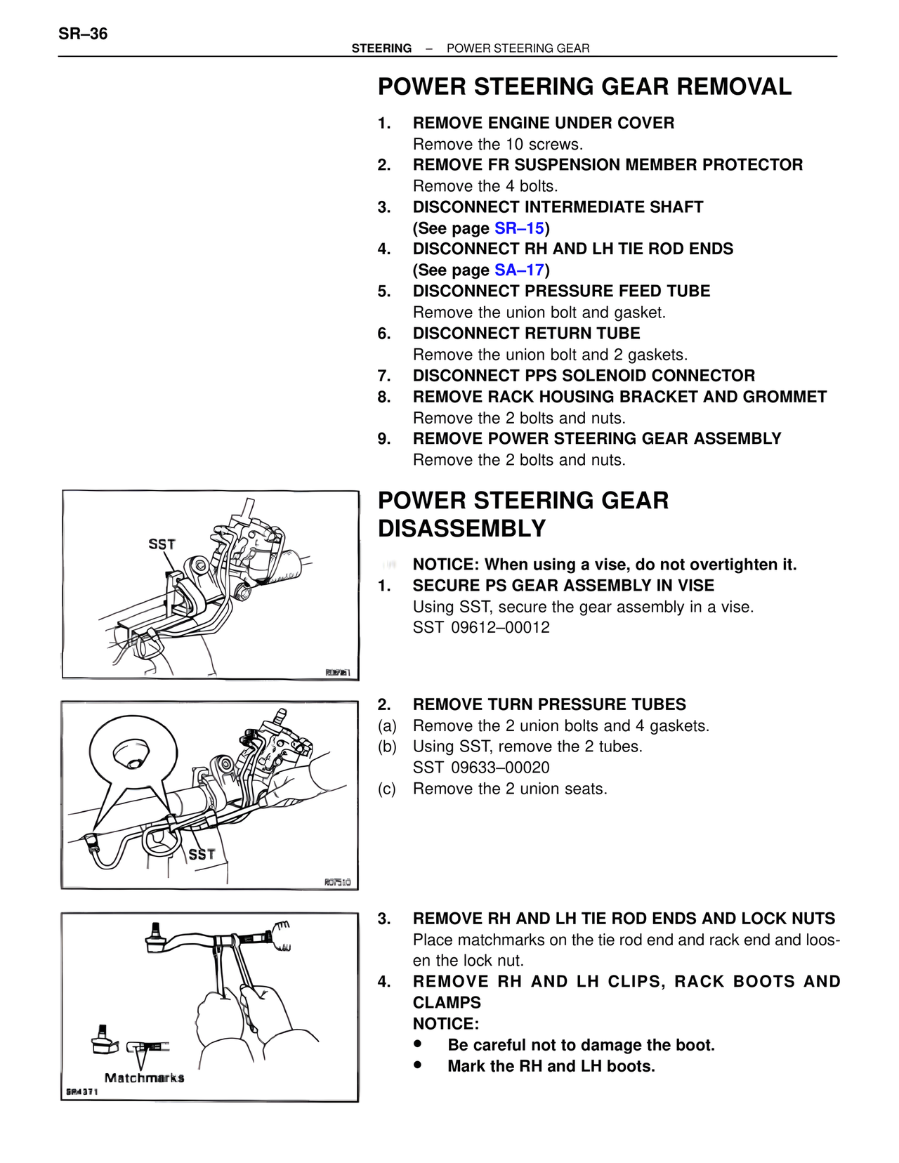
3. REMOVE RH AND LH TIE ROD ENDS AND LOCK NUTS
Place matchmarks on the tie rod end and rack end and loosen the lock nut.
4. REMOVE RH AND LH CLIPS, RACK BOOTS AND CLAMPS
NOTICE:
• Be careful not to damage the boot.
• Mark the RH and LH boots.
SST
R06961
SST
R07510
Matchmarks
SR4371