SR–45
STEERING – POWER STEERING GEAR
Brass Bar
(c) Using a brass bar and hammer, stake the washer.
NOTICE: Avoid any impact to the rack.
16. INSTALL RH AND LH RACK BOOTS, CLAMPS AND CLIPS
(a) Ensure that the steering rack hole is not clogged with grease.
HINT: If the hole is clogged, the pressure inside the boot will
change after it is assembled and the steering wheel turned.
(b) Install the boot.
NOTICE: Be careful not to damage or twist the boot.
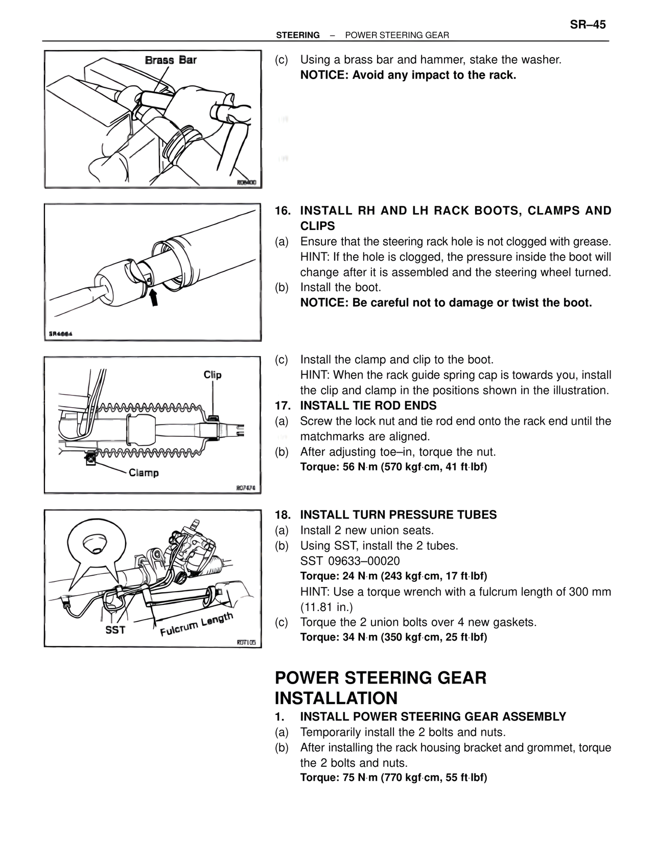
(c) Install the clamp and clip to the boot.
HINT: When the rack guide spring cap is towards you, install
the clip and clamp in the positions shown in the illustration.
Clip
Clamp
17. INSTALL TIE ROD ENDS
(a) Screw the lock nut and tie rod end onto the rack end until the
matchmarks are aligned.
(b) After adjusting toe–in, torque the nut.
Torque: 56 N·m (570 kgf·cm, 41 ft·lbf)
18. INSTALL TURN PRESSURE TUBES
(a) Install 2 new union seats.
(b) Using SST, install the 2 tubes.
SST 09633–00020
Torque: 24 N·m (243 kgf·cm, 17 ft·lbf)
HINT: Use a torque wrench with a fulcrum length of 300 mm
(11.81 in.)
(c) Torque the 2 union bolts over 4 new gaskets.
Torque: 34 N·m (350 kgf·cm, 25 ft·lbf)
SST Fulcrum Length
POWER STEERING GEAR
INSTALLATION
1. INSTALL POWER STEERING GEAR ASSEMBLY
(a) Temporarily install the 2 bolts and nuts.
(b) After installing the rack housing bracket and grommet, torque
the 2 bolts and nuts.
Torque: 75 N·m (770 kgf·cm, 55 ft·lbf)