SA-49
SUSPENSION AND AXLE — REAR DRIVE SHAFT
(c) Using SST, an extension bar and a press, press out the
inboard joint from the drive shaft.
SST 09726–12022 (09726–01030)
SST
R00191
(d) Mount the inboard joint in a soft jaw vise.
(e) Using a screwdriver and hammer, tap out the inboard joint
cover from the inboard joint.
NOTICE: Make sure the cage and inner race are not posi-
tioned too much to one side of the outer race.
5. REMOVE BOOTS FROM DRIVE SHAFT
Remove the inboard joint boot and outboard boot.
SA0726
Matchmarks
SA0721
REAR DRIVE SHAFT ASSEMBLY
1. ASSEMBLE INBOARD JOINT
If the joint has come apart, reassemble it in the following or-
der.
(a) Align the matchmarks placed before removal.
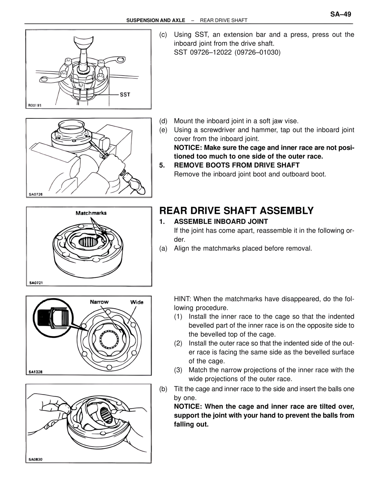
Narrow Wide
SA1328
HINT: When the matchmarks have disappeared, do the fol-
lowing procedure.
(1) Install the inner race to the cage so that the indented
bevelled part of the inner race is on the opposite side to
the bevelled top of the cage.
(2) Install the outer race so that the indented side of the out-
er race is facing the same side as the bevelled surface
of the cage.
(3) Match the narrow projections of the inner race with the
wide projections of the outer race.
(b) Tilt the cage and inner race to the side and insert the balls one
by one.
NOTICE: When the cage and inner race are tilted over,
support the joint with your hand to prevent the balls from
falling out.
SA0830