SA–50
SUSPENSION AND AXLE – REAR DRIVE SHAFT
2. TEMPORARILY INSTALL NEW BOOTS AND NEW BOOT CLAMPS
(a) Place 4 new boot clamps to boots.
HINT: Before installing the boots, wrap vinyl tape around the spline of the shaft to prevent damaging the boots.
(b) Install 2 boots to the drive shaft.
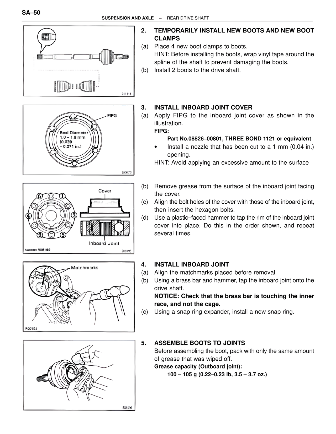
3. INSTALL INBOARD JOINT COVER
(a) Apply FIPG to the inboard joint cover as shown in the illustration.
FIPG:
Part No.08826–00801, THREE BOND 1121 or equivalent
• Install a nozzle that has been cut to a 1 mm (0.04 in.) opening.
HINT: Avoid applying an excessive amount to the surface
FIPG
Seal Diameter
1.0 – 1.8 mm
(0.039
– 0.071 in.)
(b) Remove grease from the surface of the inboard joint facing the cover.
(c) Align the bolt holes of the cover with those of the inboard joint, then insert the hexagon bolts.
(d) Use a plastic–faced hammer to tap the rim of the inboard joint cover into place. Do this in the order shown, and repeat several times.
Cover
① ②
③ ④
⑤ ⑥
Inboard Joint
4. INSTALL INBOARD JOINT
(a) Align the matchmarks placed before removal.
(b) Using a brass bar and hammer, tap the inboard joint onto the drive shaft.
NOTICE: Check that the brass bar is touching the inner race, and not the cage.
(c) Using a snap ring expander, install a new snap ring.
Matchmarks
5. ASSEMBLE BOOTS TO JOINTS
Before assembling the boot, pack with only the same amount of grease that was wiped off.
Grease capacity (Outboard joint):
100 – 105 g (0.22–0.23 lb, 3.5 – 3.7 oz.)