ENGINE – SFI SYSTEM (2JZ–GTE)
EG–293
Turn
(d) Gradually turn the sensor clockwise until the ohmmeter deflects, and secure it with the 2 set screws.
0.54 or 0.70 mm
(e) Recheck the continuity between terminals IDL and E2.
Clearance between lever and stop screw | Continuity (IDL–E2)
0.54 mm (0.021 in.) | Continuity
0.70 mm (0.028 in.) | No continuity
(f) Reconnect the vacuum hose to the throttle body.
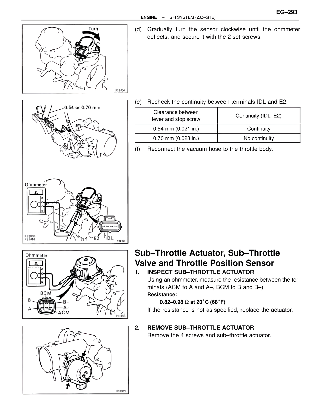
Ohmmeter
E2 IDL
Ohmmeter
BCM
B–
B
A–
A
ACM
Sub–Throttle Actuator, Sub–Throttle Valve and Throttle Position Sensor
1. INSPECT SUB–THROTTLE ACTUATOR
Using an ohmmeter, measure the resistance between the terminals (ACM to A and A–, BCM to B and B–).
Resistance:
0.82–0.98 Ω at 20°C (68°F)
If the resistance is not as specified, replace the actuator.
2. REMOVE SUB–THROTTLE ACTUATOR
Remove the 4 screws and sub–throttle actuator.