EG–415
ENGINE – 2JZ–GE ENGINE TROUBLESHOOTING
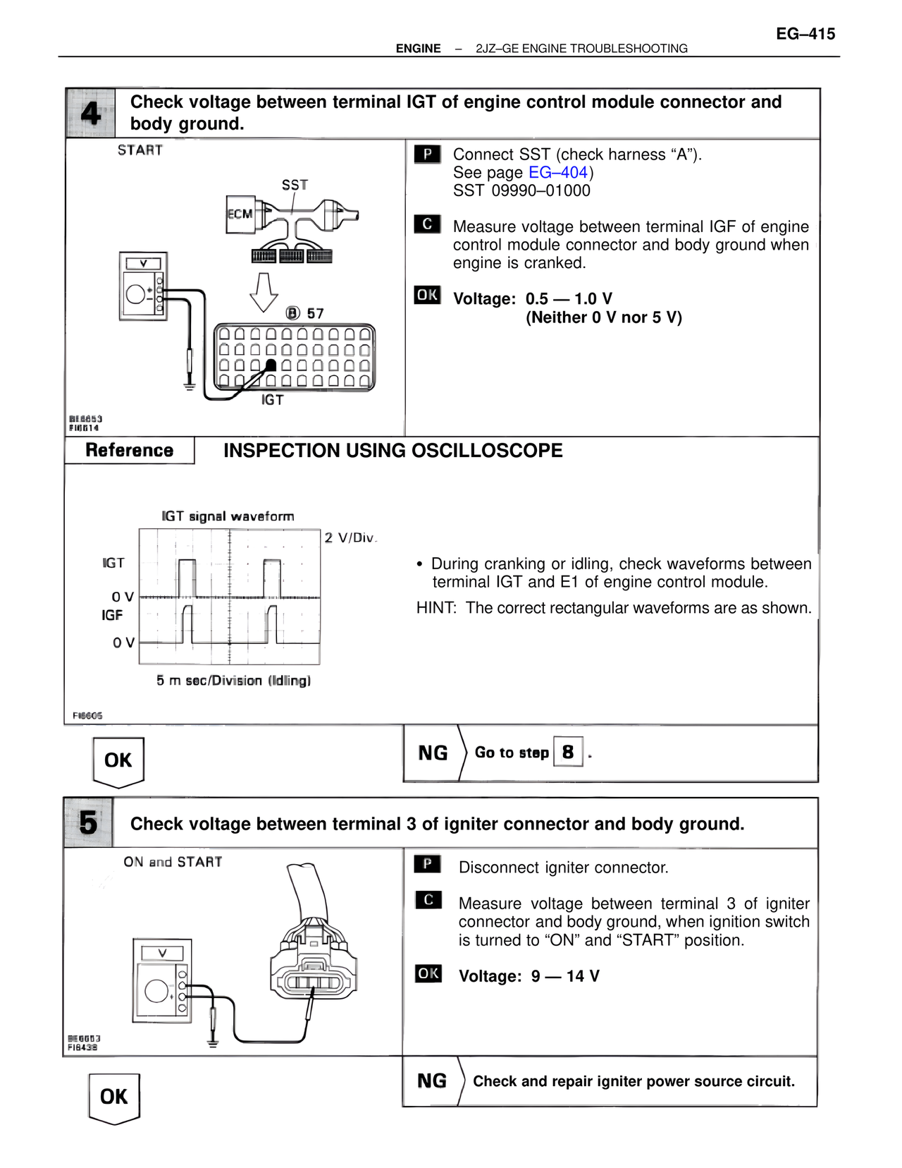
4 Check voltage between terminal IGT of engine control module connector and body ground.
START
SST
ECM
B 57
IGT
BE6653
FI0614
P Connect SST (check harness "A").
See page EG–404)
SST 09990–01000
C Measure voltage between terminal IGF of engine control module connector and body ground when engine is cranked.
OK Voltage: 0.5 — 1.0 V
(Neither 0 V nor 5 V)
Reference INSPECTION USING OSCILLOSCOPE
IGT signal waveform
2 V/Div.
IGT
0 V
IGF
0 V
5 m sec/Division (Idling)
FI6605
• During cranking or idling, check waveforms between terminal IGT and E1 of engine control module.
HINT: The correct rectangular waveforms are as shown.
OK NG Go to step 8 .
5 Check voltage between terminal 3 of igniter connector and body ground.
ON and START
BE6653
FI6438
P Disconnect igniter connector.
C Measure voltage between terminal 3 of igniter connector and body ground, when ignition switch is turned to "ON" and "START" position.
OK Voltage: 9 — 14 V
OK NG Check and repair igniter power source circuit.