DTC 52 53 55 Knock Sensor Circuit
CIRCUIT DESCRIPTION
Knock sensors are fitted one each to the front and rear of the left side of the cylinder block to detect engine knocking. This sensor contains a piezoelectric element which generates a voltage when it becomes deformed, which occurs when the cylinder block vibrates due to knocking. If engine knocking occurs, ignition timing is retarding to suppress it.
DTC No. | Diagnostic Trouble Code Detecting Condition | Trouble Area
52 | No No.1 knock sensor signal to ECM for 4 crank revolutions with engine speed between 2,050 rpm and 5,950 rpm | • Open or short in No.1 knock sensor circuit
• No.1 knock sensor (Looseness)
• ECM
53 | Engine control computer (for knock control) malfunction at engine speed between 650 rpm and 5,200 rpm | • ECM
55 | No No.2 knock sensor signal to ECM for 4 crank revolutions with engine speed between 2,050 rpm and 5,950 rpm | • Open or short No.2 knock sensor circuit
• No.2 knock sensor (looseness)
• ECM
If the ECM detects the above diagnosis conditions, it operates the fail safe function in which the corrective retard angle value is set to the maximum value.
DIAGNOSTIC TROUBLE CODE DETECTION DRIVING PATTERN
Purpose of the driving pattern.
(a) To simulate diagnostic trouble code detecting condition after diagnostic trouble code is recorded.
(b) To check that the malfunction is corrected when the repair is completed by confirming that diagnostic trouble code is no longer detected.
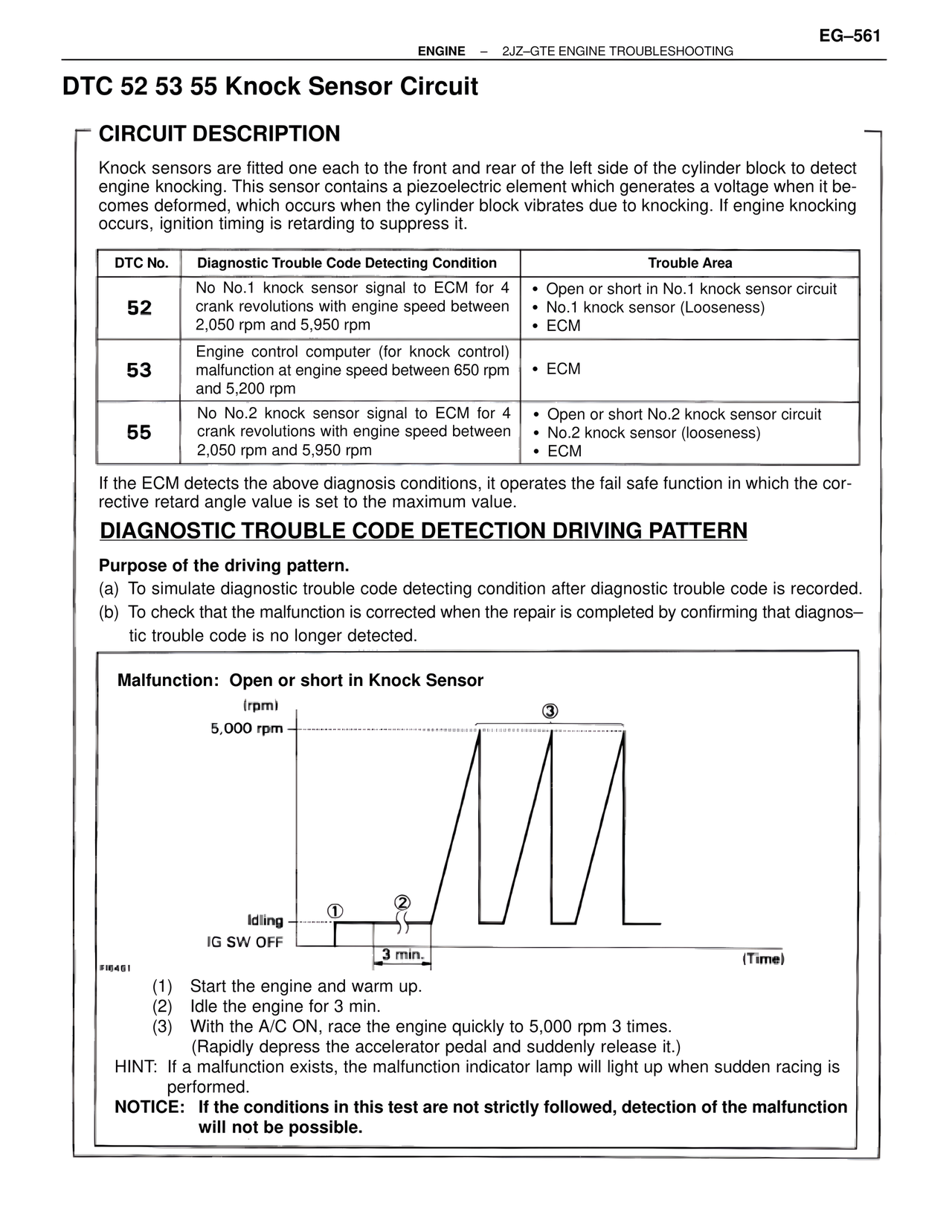
Malfunction: Open or short in Knock Sensor
(rpm)
5,000 rpm
③
Idling ① ②
IG SW OFF
3 min.
(Time)
FI6461
(1) Start the engine and warm up.
(2) Idle the engine for 3 min.
(3) With the A/C ON, race the engine quickly to 5,000 rpm 3 times.
(Rapidly depress the accelerator pedal and suddenly release it.)
HINT: If a malfunction exists, the malfunction indicator lamp will light up when sudden racing is performed.
NOTICE: If the conditions in this test are not strictly followed, detection of the malfunction will not be possible.