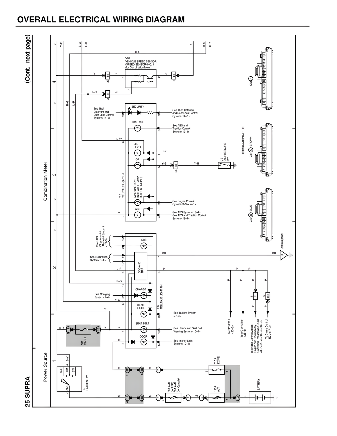
OVERALL ELECTRICAL WIRING DIAGRAM
(Cont. next page)
25 SUPRA
Combination Meter
Power Source
V10
VEHICLE SPEED SENSOR
(SPEED SENSOR NO. 1
for Combination Meter)
See Theft
Deterrent and
Door Lock Control
System<14-2>
SECURITY
TRAC OFF
OIL LEVEL
OIL
T5 TELLTALE LIGHT LH
MALFUNCTION
INDICATOR LAMP
(CHECK ENGINE)
ABS
See SRS
(Supplemental
Restraint System)
<13-3>
SRS
See Illumination
System<8-4>
ODO AND
TRIP
See Charging
System<1-4>
CHARGE
REAR
LIGHT
T6 TELLTALE LIGHT RH
SEAT BELT
DOOR
See Theft Deterrent
and Door Lock Control
System<14-2>
See ABS and
Traction Control
System<19-4>
See Engine Control
System<3-3><4-3>
See ABS System<18-4>
See ABS and Traction Control
System<19-4>
See Taillight System
<7-3>
See Unlock and Seat Belt
Warning System<10-1>
See Interior Light
System<10-1>
O.2 PRESSURE
ON
COMBINATION METER
BROWN
C1
BLUE
C10
C12
Left kick panel
BR
P
To PPS ECU
<4-5>
To A/C Amplifier
<25-5>
To Engine Control Module
(Engine and Electronics)
<3-7><4-7><15-2><16-2>
To Cruise Control
ECU<17-3>
B-Y
10A
GAUGE
ACC
IG1
ST1
T9 IGNITION SW
7 AM1
4 B-Y
7.5A DOME
100A AM1
80A AM1
(for Canada)
120A ALT
BATTERY
Y-G
Y
L-W
L-R
R-G
R-Y
Y-G
L-R
L-R
R-G
L-W
Y
Y
Y
Y
L-R
R-G
Y-G
Y
B-Y
Y
R
W
R
W
P
BR
P
B
W
R