BE–153
BODY ELECTRICAL SYSTEM – THEFT DETERRENT AND DOOR LOCK CONTROL SYSTEM
INSPECTION PROCEDURES
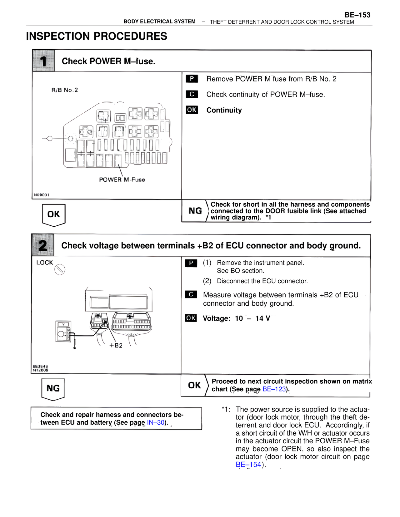
1 Check POWER M–fuse.
R/B No.2
POWER M-Fuse
N09001
P Remove POWER M fuse from R/B No. 2
C Check continuity of POWER M–fuse.
OK Continuity
OK
NG Check for short in all the harness and components connected to the DOOR fusible link (See attached wiring diagram). *1
2 Check voltage between terminals +B2 of ECU connector and body ground.
LOCK
+B2
BE3843
N12009
P (1) Remove the instrument panel.
See BO section.
(2) Disconnect the ECU connector.
C Measure voltage between terminals +B2 of ECU connector and body ground.
OK Voltage: 10 – 14 V
NG
OK Proceed to next circuit inspection shown on matrix chart (See page BE–123).
Check and repair harness and connectors between ECU and battery (See page IN–30).
*1: The power source is supplied to the actuator (door lock motor, through the theft deterrent and door lock ECU. Accordingly, if a short circuit of the W/H or actuator occurs in the actuator circuit the POWER M–Fuse may become OPEN, so also inspect the actuator (door lock motor circuit on page BE–154).