BE–155
BODY ELECTRICAL SYSTEM – THEFT DETERRENT AND DOOR LOCK CONTROL SYSTEM
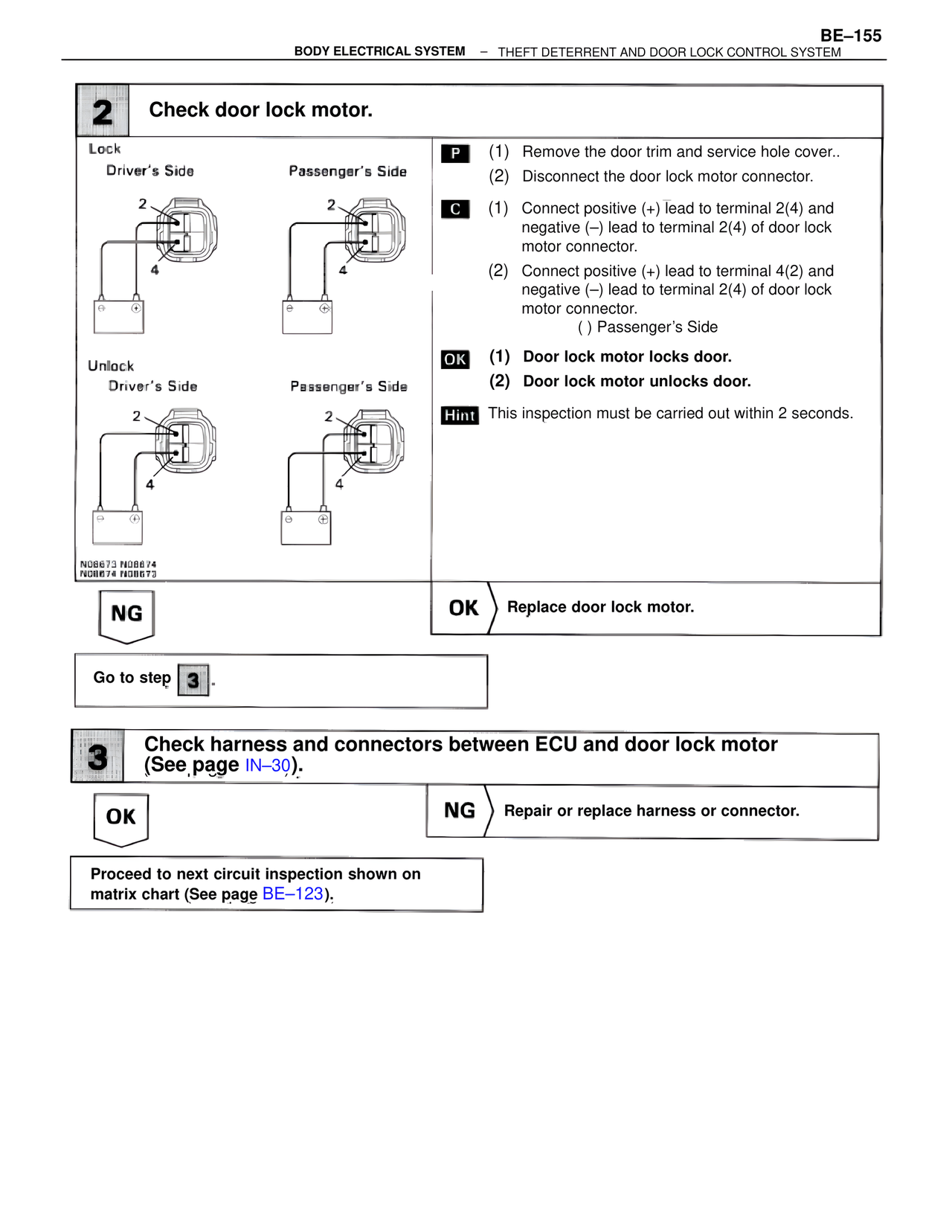
2 Check door lock motor.
Lock
Driver's Side Passenger's Side
2 2
4 4
Unlock
Driver's Side Passenger's Side
2 2
4 4
N08673 N08674
N08674 N08673
P (1) Remove the door trim and service hole cover..
(2) Disconnect the door lock motor connector.
C (1) Connect positive (+) lead to terminal 2(4) and
negative (–) lead to terminal 2(4) of door lock
motor connector.
(2) Connect positive (+) lead to terminal 4(2) and
negative (–) lead to terminal 2(4) of door lock
motor connector.
( ) Passenger's Side
OK (1) Door lock motor locks door.
(2) Door lock motor unlocks door.
Hint This inspection must be carried out within 2 seconds.
NG OK Replace door lock motor.
Go to step 3 .
3 Check harness and connectors between ECU and door lock motor
(See page IN–30).
OK NG Repair or replace harness or connector.
Proceed to next circuit inspection shown on
matrix chart (See page BE–123).