IN–26
INTRODUCTION – HOW TO TROUBLESHOOT ECU CONTROLLED SYSTEMS
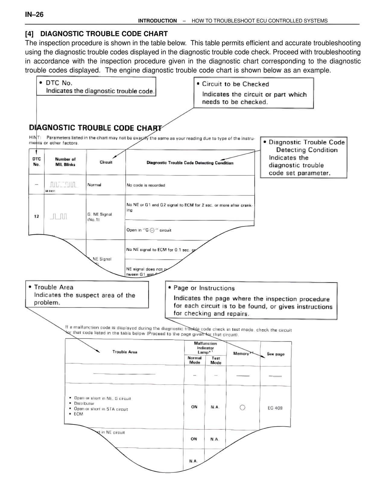
[4] DIAGNOSTIC TROUBLE CODE CHART
The inspection procedure is shown in the table below. This table permits efficient and accurate troubleshooting using the diagnostic trouble codes displayed in the diagnostic trouble code check. Proceed with troubleshooting in accordance with the inspection procedure given in the diagnostic chart corresponding to the diagnostic trouble codes displayed. The engine diagnostic trouble code chart is shown below as an example.
• DTC No.
Indicates the diagnostic trouble code.
• Circuit to be Checked
Indicates the circuit or part which needs to be checked.
DIAGNOSTIC TROUBLE CODE CHART
HINT: Parameters listed in the chart may not be exactly the same as your reading due to type of the instruments or other factors.
• Diagnostic Trouble Code Detecting Condition
Indicates the diagnostic trouble code set parameter.
DTC No. | Number of MIL Blinks | Circuit | Diagnostic Trouble Code Detecting Condition
– | [normal blink pattern] | Normal | No code is recorded
12 | [blink pattern] | G, NE Signal (No.1) | No NE or G1 and G2 signal to ECM for 2 sec. or more after cranking
Open in "G ⊖" circuit
| | NE Signal | No NE signal to ECM for 0.1 sec. or–
NE signal does not p–
tween G1 and–
• Trouble Area
Indicates the suspect area of the problem.
• Page or Instructions
Indicates the page where the inspection procedure for each circuit is to be found, or gives instructions for checking and repairs.
If a malfunction code is displayed during the diagnostic trouble code check in test mode, check the circuit for that code listed in the table below (Proceed to the page given for that circuit).
Trouble Area | Malfunction Indicator Lamp*1 | Memory*2 | See page
| Normal Mode | Test Mode | |
– | – | —— | ——
• Open or short in NE, G circuit
• Distributor
• Open or short in STA circuit
• ECM
ON | N.A. | ○ | EG-409
–d in NE circuit
ON | N.A.
N.A.