EG–248
ENGINE – SFI SYSTEM (2JZ–GE)
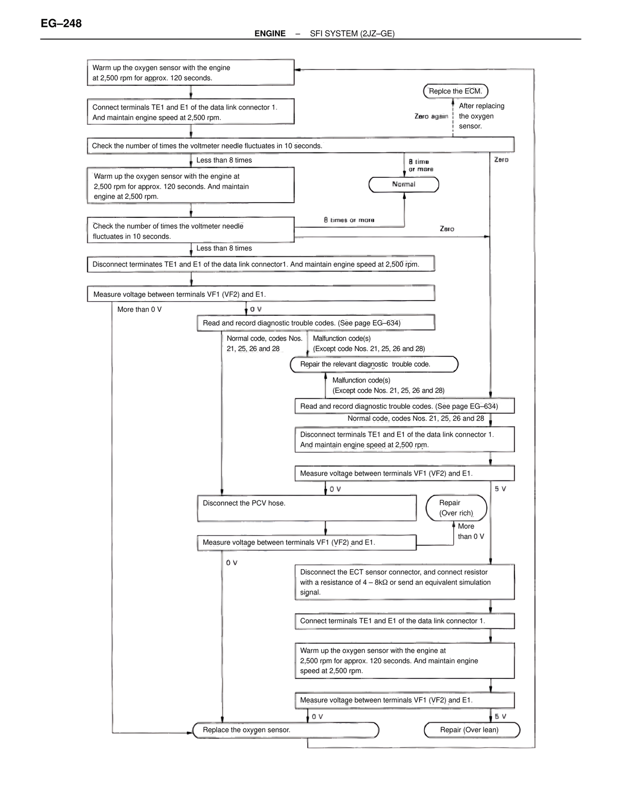
Warm up the oxygen sensor with the engine
at 2,500 rpm for approx. 120 seconds.
Connect terminals TE1 and E1 of the data link connector 1.
And maintain engine speed at 2,500 rpm.
Check the number of times the voltmeter needle fluctuates in 10 seconds.
Less than 8 times
8 times
or more
Normal
Warm up the oxygen sensor with the engine at
2,500 rpm for approx. 120 seconds. And maintain
engine at 2,500 rpm.
8 times or more
Zero
Check the number of times the voltmeter needle
fluctuates in 10 seconds.
Less than 8 times
Disconnect terminates TE1 and E1 of the data link connector1. And maintain engine speed at 2,500 rpm.
Measure voltage between terminals VF1 (VF2) and E1.
More than 0 V
0 V
Read and record diagnostic trouble codes. (See page EG–634)
Normal code, codes Nos.
21, 25, 26 and 28
Malfunction code(s)
(Except code Nos. 21, 25, 26 and 28)
Repair the relevant diagnostic trouble code.
Malfunction code(s)
(Except code Nos. 21, 25, 26 and 28)
Read and record diagnostic trouble codes. (See page EG–634)
Normal code, codes Nos. 21, 25, 26 and 28
Disconnect terminals TE1 and E1 of the data link connector 1.
And maintain engine speed at 2,500 rpm.
Measure voltage between terminals VF1 (VF2) and E1.
0 V
5 V
Disconnect the PCV hose.
Repair
(Over rich)
More
than 0 V
Measure voltage between terminals VF1 (VF2) and E1.
0 V
Disconnect the ECT sensor connector, and connect resistor
with a resistance of 4 – 8kΩ or send an equivalent simulation
signal.
Connect terminals TE1 and E1 of the data link connector 1.
Warm up the oxygen sensor with the engine at
2,500 rpm for approx. 120 seconds. And maintain engine
speed at 2,500 rpm.
Measure voltage between terminals VF1 (VF2) and E1.
0 V
5 V
Replace the oxygen sensor.
Repair (Over lean)
Replce the ECM.
Zero again
After replacing
the oxygen
sensor.
Zero