MT1–20
W58 MANUAL TRANSMISSION – COMPONENT PARTS REMOVAL
(b) Remove the spacer.
(c) Using 2 screwdrivers and a hammer, tap out the snap ring.
INSTALLATION HINT: Select a snap ring that will allow minimum axial play.
Mark | Thickness mm (in.)
2 | 2.06–2.11 (0.0811–0.0831)
3 | 2.12–2.17 (0.0835–0.0854)
4 | 2.18–2.23 (0.0858–0.0878)
5 | 2.24–2.29 (0.0882–0.0902)
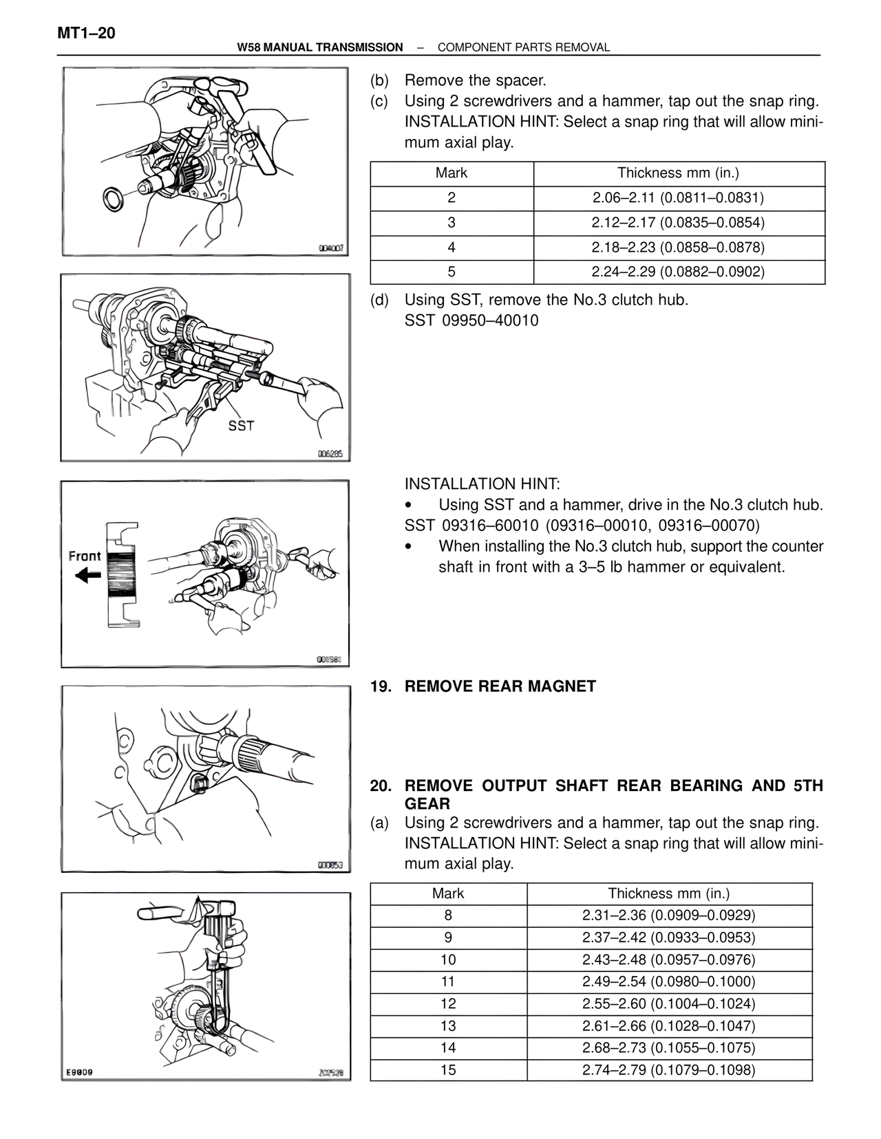
(d) Using SST, remove the No.3 clutch hub.
SST 09950–40010
INSTALLATION HINT:
• Using SST and a hammer, drive in the No.3 clutch hub.
SST 09316–60010 (09316–00010, 09316–00070)
• When installing the No.3 clutch hub, support the counter shaft in front with a 3–5 lb hammer or equivalent.
Front
SST
19. REMOVE REAR MAGNET
20. REMOVE OUTPUT SHAFT REAR BEARING AND 5TH GEAR
(a) Using 2 screwdrivers and a hammer, tap out the snap ring.
INSTALLATION HINT: Select a snap ring that will allow minimum axial play.
Mark | Thickness mm (in.)
8 | 2.31–2.36 (0.0909–0.0929)
9 | 2.37–2.42 (0.0933–0.0953)
10 | 2.43–2.48 (0.0957–0.0976)
11 | 2.49–2.54 (0.0980–0.1000)
12 | 2.55–2.60 (0.1004–0.1024)
13 | 2.61–2.66 (0.1028–0.1047)
14 | 2.68–2.73 (0.1055–0.1075)
15 | 2.74–2.79 (0.1079–0.1098)