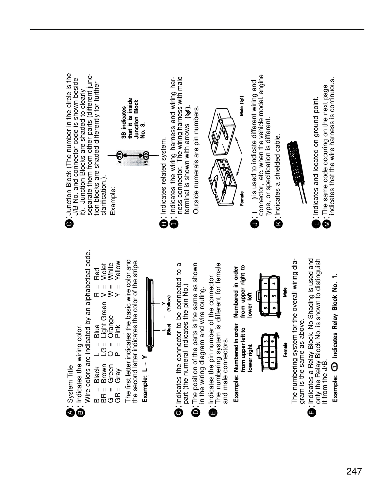
A: System Title
B: Indicates the wiring color.
Wire colors are indicated by an alphabetical code.
B = Black L = Blue R = Red
BR = Brown LG = Light Green V = Violet
G = Green O = Orange W = White
GR = Gray P = Pink Y = Yellow
The first letter indicates the basic wire color and
the second letter indicates the color of the stripe.
Example: L – Y
(Blue)
(Yellow)
C: Indicates the connector to be connected to a
part (the numeral indicates the pin No.)
D: The position of the parts is the same as shown
in the wiring diagram and wire routing.
E: Indicates the pin number of the connector.
The numbering system is different for female
and male connectors.
Example: Numbered in order
from upper left to
lower right
Numbered in order
from upper right to
lower left
Male
Female
The numbering system for the overall wiring dia-
gram is the same as above.
F: Indicates a Relay Block. No Shading is used and
only the Relay Block No. is shown to distinguish
it from the J/B.
Example: O Indicates Relay Block No. 1.
G: Junction Block (The number in the circle is the
J/B No. and connector code is shown beside
it). Junction Blocks are shaded to clearly
separate them from other parts (different junc-
tion blocks are shaded differently for further
clarification.).
Example:
6 (3B) 15 (3B)
3B indicates
that it is inside
Junction Block
No. 3.
H: Indicates related system.
I: Indicates the wiring harness and wiring har-
ness connector. The wiring harness with male
terminal is shown with arrows (Y).
Outside numerals are pin numbers.
Male (Y)
Female
J: ( ) is used to indicate different wiring and
connector, etc. when the vehicle model, engine
type, or specification is different.
K: Indicates a shielded cable.
L: Indicates and located on ground point.
M: The same code occuring on the next page
indicates that the wire harness is continuous.
247